Download
1 / 28
280 likes | 387 Views
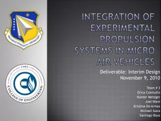
Integration of experimental propulsion systems in micro air vehicles. Design for Six Sigma Approach- DMAVD Define Phase October 12, 2010 Team # 3 Erica Cosmutto Hunter Metzger Joel Ware Kristina De Armas Michael Isaza Santiago Baus. Interdisciplinary senior design Meet our Team!.

E N D
Integration of experimental propulsion systems in micro air vehicles Design for Six Sigma Approach- DMAVD Define Phase October 12, 2010 Team # 3 Erica Cosmutto Hunter Metzger Joel Ware Kristina De Armas Michael Isaza Santiago Baus
Interdisciplinary senior designMeet our Team! • Santiago Baus • Industrial Engineering Student • IE Team Leader • Director of Quality • Joel Ware • Mechanical Engineering Student • ME Treasurer • Director of Design • Kristina De Armas • Industrial Engineering Student • IE Data Organizer • Director of Six Sigma Methods • Erica Cosmutto • Mechanical Engineering Student • ME Team Leader • Director of Analysis • Hunter Metzger • Mechanical Engineering Student • ME Data Organizer • Director of Component Selection • Michael Isaza • Industrial Engineering Student • IE Treasurer • Director of Manufacturing
PRESENTATION OVERVIEW • Introduction to Micro Air Vehicles (MAVs) • What is DMADV? • Project Charter • Communication Strategy • Compelling Need • Process Documentation • Customer Requirements • Mechanical Elements • Future Plans • References • Questions U.S. Air Force, Bud Sized Spy
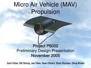
Micro Air Vehicles (MAVs) • Class of unmanned aerial vehicles (UAVs) • Intelligent robots of the sky • Multi-purpose • Military • Research • Government • Commercial • Max wing span of 15cm (~6 inches) • Insect-sized aircraft expected in the future • Extremely discrete operations
What is DMADV? • Directly related to Design for Six Sigma (DFSS) • One of the two methodologies of Six Sigma • Extremely effective way to create a new product or a new process design • Goals • Design to be predictable • Defect free
Business Case • Eglin Air Force Base • Integrate components into a Micro Air Vehicle • Design 4 basic MAV models • One distinct fuselage design • Variable placements of electric ducted fan • Failure to experiment on new propulsion systems • Results in: • Set back in technology advancement • Loss of potential field reconnaissance
Opportunity statement • MAVs were first designed in 1993 • Experiment integrating new propulsion systems in MAVs • Electric ducted fan • Carbon fiber fuselage • Proper implementation of an effective propulsion system • MAVs undergo mass production • Revolutionize the way the military approaches certain situations
Goal statement • Design and develop the most efficient and flight ready MAV by integrating an experimental propulsion system • Input Variables • Basic MAV requirements • Eglin Air Force requirements • ME Department Requirements • IE Department Requirements
Project scope • Integrate an electric ducted fan into the fuselage of a Micro Air Vehicle (MAV) • Our Focus • Fuselage design • Duct design • Integrating electronics and fan into the fuselage • Goals • Design four types of fuselage (choose one to manufacture) • Each will demonstrate the effectiveness of the propulsion system and duct design • Out of Scope • Design and development of wings • Take off and landing • Servo selection
Project plan • Start Date: September 7, 2010 • Define Phase: October 19, 2010- 6 weeks • Measure Phase: November 30, 2010- 6 weeks • Analyze, Design, Verify: Spring 2011
Communication strategy • Effective communication strategy • Defines the message to be delivered and the method of delivery
Compelling need • “Unless you convince me I am worse off, I won’t change” • MAVs will soon play an important role in future warfare • Increase the war fighters situational awareness • Facilitate rapid and precise engagement • Decrease amount of fatalities • Use threat opportunity matrix as tool
Threat Opportunity Matrix Threats Opportunity Short Term Long Term
Process documentationSipoc diagram Start Boundary: Proposal End Boundary: Integration of Components Suppliers Inputs Process Outputs Customers • Pre-designed wings • Fuselage designs • Battery • Speed & flight control • Electric ducted fan • Constraints • Duct Designs • CAD, Pro-E, Catia sketches • 3D Printing • Fuselage & Duct Manufacture Integration of Components • Eglin Air Force Base • HPMI • Tower Hobbies • Flight ready MAV • Eglin Air Force Base
Customer requirements • Important to customer • Establishes a target • Numerous requirements • Brainstorm cause and effects • How should we measure? • Tools used to organize and measure • Fishbone Diagram • House of Quality • Results obtained from tools • Max relative weight: 10.3 • Focus on width and weight
Component selection • 4kg of Thrust • 90mm Inner Diameter • 29.6V • 65A Electronic Speed Control Electric Ducted Fan Battery www.towerhobbies.com www.hobbypartz.com www.airshowrc.com • 8S Li-Po Battery (29.6V) • 30C Current • 5000 mAh • 6-12 Cell Li-Po (22.2V – 44.4V) • 150A
Weight and cost analysis • Constrained to a total of 10 lbs • Average density of carbon fiber: 0.065 lbs/in3 • By V=m/ρ → carbon fiber cannot exceed 93.84 in3
Fuselage and Ideal duct design • Fuselage Design • Material (Carbon Fiber Composite) • Geometry of Fuselage • Ideal Duct Design • High Pressure after fan • Hole in front of fan (more air being pulled in by fan) • Efficient • Small diameter
Integration of Components • One set of components • Hatch to remove electrical components • Velcro
Design Concepts Design 3 • Choose one fuselage design • Vary duct design Design 1 Design 4 Design 2
Future plans • Finalize EDF and purchase components • Detailed Design (Comsol, Catia) • Analysis (mass flow, thrust, weight, dimensions) • Create molds • Assemble • Test • Explore manufacturing process • DAMES • Optimizing facility layout
Resources • "76mm Aluminum Alloy Electric Ducted Fan." Nitro RC Planes, Inc. 2010. Web. 05 Oct. 2010. <http://www.nitroplanes.com/lealalel76du.html>. • Çengel, Yunus A., and Robert H. Turner. Fundamentals of Thermal-fluid Sciences. 3rd ed. Boston: McGraw-Hill, 2001. Print. • Draganfly Innovations Inc. RCToys.com Sells RC Airplanes RC Blimps RC Helicopters & Parts. 2008. Web. 07 Oct. 2010. <http://www.rctoys.com/pr/category/rc-information/rc-hobby-parts-component-info/>. • "Electric Ducted Fan Jet." RC Hobby Universe Guide to RC Airplanes, Helicopters, Boats, Cars and Trucks! 2006. Web. 07 Oct. 2010. <http://www.rc-hobby-universe.com/electric-ducted-fan-jet.html>. • “Integrating GPS with MAVs.”<http://www.mil.ufl.edu/~number9/mav/>. • “RC Hobby Universe.” <http://www.rc-hobby universe.com/electric-ducted-fan-jet.html>.