Download
1 / 32
450 likes | 1.16k Views
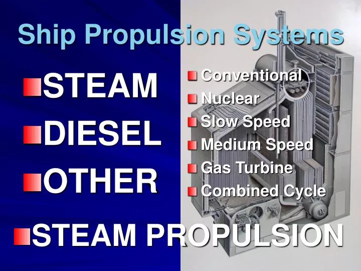
STEAM DIESEL OTHER. Conventional Nuclear Slow Speed Medium Speed Gas Turbine Combined Cycle. Ship Propulsion Systems. STEAM PROPULSION. Main Steam Cycle. Generation segment Expansion segment Condensate segment Feedwater segment. W. H. H. H. W. W. H. Main Steam Cycle.

E N D
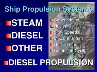
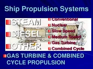
STEAM DIESEL OTHER Conventional Nuclear Slow Speed Medium Speed Gas Turbine Combined Cycle Ship Propulsion Systems • STEAM PROPULSION
Main Steam Cycle Generation segment Expansion segment Condensate segment Feedwater segment
W H H H W W H Main Steam Cycle EXPANSION GENERATION HP liquid HP vapor Superheat HP vapor HP vapor LP vapor Thermal Mechanical LP liquid HP liquid continue raising Temp & Press LP vapor LP liquid Begin raising Temp & Press FEEDWATER CONDENSATE
MAIN CONDENSER 90oF Superheated vapor: 590 psig; 880oF Mn Stm Cycle SUPERHEATER EXP MAIN STM GEN MAIN ENGINE HP TG steam Aux steam Saturated vapor: 600 psig; 490oF LP BOILER Saturated vapor: 28.5”Hg; 92oF Exhaust Stm Saturated liquid: 28.5”Hg; 92oF HP Heaters 650 - 750 psig DC HTR Main Condensate Pump 50 psig Main Feed Pump FWTR COND LP Heaters
SUPERHEATER MAIN STM TG steam Aux steam BOILER MAIN CONDENSER Mn Stm Cycle EXP GEN MAIN ENGINE HP LP Exhaust Stm HP Heaters DC HTR Main Condensate Pump Main Feed Pump FWTR COND LP Heaters
DRUM TYPE BOILER (TSES VI) FURNACE FURNACE AIR FUEL
DRUM TYPE BOILER (TSES VI) STEAM DRUM GENERATING TUBES WATER-WALL TUBES WATER DRUM
DRUM TYPE BOILER (TSES VI) superheater
DRUM TYPE BOILER (TSES IV) MAIN STEAM STOP VALVE SUPERHEATER VENT VALVE SUPERHEATER SAFETY VALVE superheater TG STEAM STOP VALVE AUX STEAM STOP VALVE
MAIN STM MAIN ENGINE HP LP Exhaust Stm MAIN CONDENSER Mn Stm Cycle SUPERHEATER EXP GEN TG steam Aux steam BOILER HP Heaters DC HTR Main Condensate Pump Main Feed Pump FWTR COND LP Heaters
Axial Flow Turbine Stm. PRESSURE Stm. VELOCITY
BLADE WHEELS NOZZEL DIAPHRAGMS 3 Stage, Impulse Turbine • Nozzles are stationary, fixed in a nozzle diaphragm attached to the turbine casing • Blades move, fitting in a wheel attached to the rotor shaft • A Stage consists of a set of nozzles & a set of blades
SUPERHEATER GEN TG steam Aux steam BOILER MAIN CONDENSER HP Heaters DC HTR Main Condensate Pump Main Feed Pump FWTR COND LP Heaters Mn Stm Cycle EXP MAIN STM MAIN ENGINE HP LP Exhaust Stm
EXP MAIN STM MAIN ENGINE LP Turbine Casing Exhaust Stm Mn Stm Cycle TSES arrangement HP ASTERN STEAM LP X-over AHEAD STEAM HP Turbine Casing Steam Chest
TSES VI HP Turbine9 impulse stages CROSS - OVER To LP Turbine STEAM CHEST IP BLEED cross-over Extraction HP BLEED 6th Stage Extraction
AHEAD ROTATION ASTERN ROTATION Astern Turbine1 Curtiss & 1 Impulse stage TSES VI LP Turbine4 impulse, 1 Transition, & 4 reaction stages LP BLEED ASTERN STEAM CROSS - OVER From HP Turbine EXHAUST TRUNK To Main Condenser
Determining Sea Speed –nozzle control valves Sea Speed – long duration (e.g., port to port) as opposed to maneuvering Throttle at fixed position (usually wide open) Nozzle C.V. opens a chamber to a set number of 1st stage nozzles Number of nozzles open corresponds to a particular engine RPM and hence sea speed LP Turbine Casing 9 X-over Nozzle Control Valves HP Turbine Casing 14 12 4 Steam Chest
1st Stage Nozzle Control Valves 14 12 9 4 + 9 = 13
Maneuvering –Ahead & Astern Throttles LP Turbine Casing ASTERN GUARDIAN VALVE ASTERN THROTTLE X-over HP Turbine Casing AHEAD THROTTLE Fixed Number of Nozzles
Maneuvering –Ahead & Astern Throttles LP Turbine Casing ASTERN GUARDIAN VALVE ASTERN THROTTLE X-over HP Turbine Casing AHEAD THROTTLE Fixed Number of Nozzles
SUPERHEATER MAIN STM MAIN ENGINE HP LP BOILER Exhaust Stm MAIN CONDENSER HP Heaters Main Condensate Pump Main Feed Pump LP Heaters Mn Stm Cycle EXP GEN TG steam Aux steam DC HTR FWTR COND
(Shell & Tube) HEAT EXCHANGER FLUID 1 HOT FLUID 2 COLD COOL • FLUID 1 gives up heat • FLUID 2 absorbs heat from FLUID 1 • Either 1 or 2 may be the PRIMARY FLUID • Either fluid may be inside or outside tubes, but there is no direct contact WARM
(Shell & Tube) HEAT EVCHANGER • HEATER: Primary fluid does not change phase, but increases in temperature (sensible heat) • Example: Fuel Oil Heater • COOLER: Primary fluid does not change phase, but decreases in temperature (sensible heat) • Example: Lube Oil Cooler • EVAPORATOR: Primary fluid changes from liquid to vapor (absorbs latent heat) • CONDENSER: Primary fluid changes from vapor to liquid (gives up latent heat)
MAIN CONDENSER Air drag line To AIR EJECTOR S.W. ovbd MAIN CIRCULATING PUMP MAIN CONDENSATE PUMP
JET PUMP (2ndt Stage) MAIN AIR EJECTOR AUX STEAM (150 psig) JET PUMP (1st Stage) AIR (VACUUM) DRAG LINE AIR VENT CONDENSATE from Main Cond. Pump INTER- CONDENSER 10–15 “Hg (VAC)0 AFTER- CONDENSER ~ 1 Atm CONDENSATE to 1st stage heater Return to CONDENSER via LOOP SEAL Drain to ADT
LP Turbine Bleed 1st STAGE HEATER (actual) 1st STAGE HEATER CONDENSATE to DC HEATER GLAND EXHAUST COND CONDENSATE from AIR EJECTOR (1st STAGE) DRAIN COOLER 3 Heat Exchangers in one casing
DC (Direct Contact) Heater • Scrubbing action of steam removes dissolved O2 from condensate • DC Heater also called Dearation Feed Tank (DFT) Auxiliary Exhaust Steam • Acts as surge tank in system (accommodates surplus or deficit of working fluid) Condensate from 1st STG HTR FEEDWATER approx. 15 psig; 250oF • Located high in machinery space, provides positive head to Feed Pump To FEED PUMP SUCTION
MAIN FEED PUMP(S) From DC HTR PORT BLR PORT BLR STBD BLR STBD BLR SUCT VALVE TURBINE DISCH MAIN FEED DISCH AUX FEED PUMP STEAM SUPP LY VALVE EXH VALVE Recirc to DC HTR AUX EXHAUST to DC HTR
almost there …. FW Reg. Valve MAIN FEED To Stm Drum (Port Boiler) ECONOMIZER Stop Valve Stop/ Check V. AUX. FEED
Economizer location…. SUPERHEATER Mn Steam GEN TG steam Aux steam BOILER ECONOMIZER DC HTR Main Feed Pump FWTR
MAIN CONDENSER Economizer VAPOR Mn Stm Cycle SUPERHEATER EXP MAIN STM GEN HP TG steam Aux steam MAIN ENGINE LP BOILER Exhaust Stm LIQUID DC HTR Main Condensate Pump Main Feed Pump AE FWTR COND 1st
MAIN CONDENSER Economizer 885oF Mn Stm Cycle 585 psig 585 psig SUPERHEATER EXP MAIN STM GEN 40 psig HP TG steam 600 psig 490oF Aux steam MAIN ENGINE LP BOILER Exhaust Stm 28.5 “Hg 92oF 380oF 240oF 15 psig 90oF 650 - 750 psig DC HTR Main Condensate Pump 120oF Main Feed Pump 160oF AE FWTR 50 psig COND 1st