Download
1 / 35
350 likes | 490 Views
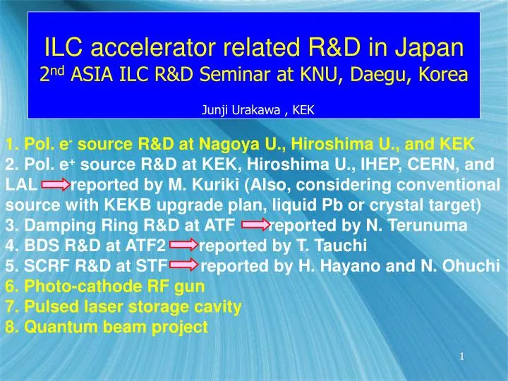
1. Pol. e - source R&D at Nagoya U., Hiroshima U., and KEK 2. Pol. e + source R&D at KEK, Hiroshima U., IHEP, CERN, and LAL reported by M. Kuriki (Also, considering conventional source with KEKB upgrade plan, liquid Pb or crystal target)

E N D
1. Pol. e- source R&D at Nagoya U., Hiroshima U., and KEK 2. Pol. e+ source R&D at KEK, Hiroshima U., IHEP, CERN, and LAL reported by M. Kuriki (Also, considering conventional source with KEKB upgrade plan, liquid Pb or crystal target) 3. Damping Ring R&D at ATF reported by N. Terunuma 4. BDS R&D at ATF2 reported by T. Tauchi 5. SCRF R&D at STF reported by H. Hayano and N. Ohuchi 6. Photo-cathode RF gun 7. Pulsed laser storage cavity 8. Quantum beam project ILC accelerator related R&D in Japan2nd ASIA ILC R&D Seminar at KNU, Daegu, Korea Junji Urakawa , KEK 1
1. Pol. e- source R&D at Nagoya U., Hiroshima U., and KEK Production of nanosecond pol.e- beam for ILC Laser ILC:6.4nC/bunch e-beam Photocathode: GaAs-GaAsP SL (Pol.max > 85%) Laser energy : 6mJ (10Hz) Bunch width(FWHM): 1.6ns Bunch charge : 8nC The SL active layer grown on a laser cutting GaAs wafer
Space charge limit Experiments & Simulations Experimental data Extracted charge of 30nC/bunch was obtained. The experimental data is a measurement of supply current to the electrode. Simulation data(GPT) Extracted charge is estimated from the number of macro-particles at 10mm downstream PC. Both results are corresponding well, therefore this simulation is almost appropriate for calculating SC effect.
Characteristics of SUS and Ti-Mo electrode Advantages of Ti-Mo electrode Darkcurrent characteristic isn’t degraded even if many breakdowns were occurred. Hardly observed dark current until breakdown was occurred.
Photocathode Lifetime Preliminary Gun:2.7x10⁻⁹Pa 2NEG:2.0x10⁻⁹Pa The photocathode lifetime seems no problem under the condition of a few micro amps beam emission.
Long-term 200keV operation became possible by employing the titanium anode and molybdenum cathode electrode. Remaining R&D : A laser system which meets fully ILC requirements. SLAC is developing. Hiroshima, and KEK are considering.
6. Photo-cathode RF gun Cs2Te Photo-cathode, 1.6 Cell S-band RF Gun Multi-bunch beam generation
100 bunches/pulse energy spread is less than 0.5%. Fig. 7 Upper-left : ICT signal of 100 bunches, upper-right : 100 bunches on the OTR screen, bottom figure : energy of each bunch in the train
Laser Pulse Stacking Chamber, 3m long S-band accelerating tube and Photo-cathode RF Gun Collision point Faraday Cup Top view ICT BPM BPM BPM BPM solenoid RF Gun PRM PRM S-band accelerating tube (3m) PRM PRM Q-magnet Q-magnet Bending magnet Cathode: Cs-Te Q-magnet Chicane e- beam Emittance measurement Side view ICT & Faraday Cup: Beam current monitor BPM: Beam position monitor PRM BPM ICT PRM: Beam Profile Monitor OTR target or Al2O3 (Cr3+ doped) Beam energy and energy spread measurement
Emittance measurement Collision point εx: 3.0 [mm・mrad] QF1 QD1 Beam current : 2.5nC/train, 3bunches Beam profile at Collision point εy: 4.7 [mm・mrad] σx: 86um σy: 36um CP1G (OTR)
Optical Circuit e- beam P-LW-CAV installed in APR2007. e- beam
X-ray Generation 43MeV end station to separate X-ray and e-beam. 33keV X-ray is deflected by Crystals. Pulsed laser stacking chamber
Laser Undulator Compact X-ray (LUCX)Project at KEK-ATF Multi-bunch photo-cathode RF Gun 43MeV Multi-bunch beam+ Super-Cavity = 33keV X-ray. X-ray Detector S-band Acc. Structure Beam size at CP 60mm in s Multi-bunch e- beam 300nC at gun At present, laser waist size is 30mm in s. We should reduce both beam size at CP down to 30mm. 33keV X-ray generation based on inverse Compton scattering was started from May 2007 with Super-Cavity. Storage Laser power 40kW, 7psec(FWHM), next step :1MW
7. Pulsed laser storage cavity 50 mJ / pulse, waist = 8 m From two-mirror cavity to four-mirror cavity under International collaboration with LAL. e- beam laser beam
Considering two-mirror cavity, reflectance R, transmissivity T, and losses L where R+T+L = 1 by energy conservation. The “bounce number” b which is defined from the round-trip power loss in a cavity, ∝ e−1/b.FSR : free spectral range If R=R1=R2
Perfect resonance : L = L laser cavity Imperfect Resonance : L ~ L laser cavity Not resonance : L ≠ L laser cavity Storage of laser pulse Resonance condition : The relationship with laser and cavity : The enhancement factor is the function of reflectivity, Δl and laser pulse width.
Achievement on related technique JFY2003 CW Laser wire beam size monitor in DR 14.7µm laser wire for X scan 5.7µm for Y scan (whole scan: 15min for X, 6min for Y) 300mW 532nm Solid-state Laser fed into optical cavity
Laser wire block diagram Free spectral range :532nm/2=266nm Line width=0.3nm optical cavity resonance is kept by piezo actuator
Experimental results(Pulse Laser Storage) Laser: Mode Lock: Passive SESAM Frequency: 357MHz Cavity length: 0.42 m Pulse width: 7.3 p sec (FWHM) Wave Length: 1064 nm Power: ~ 6W SESAM: SEmi-conductor Saturable Absorber Mirrors
Ext. Cavity: Cavity: Super Invar Cavity length: 420mm Mirrors: Reflectivity: 99.9%, 99.9% (maybe, 99.98%) Curvature: 250 mm (ω0 = 180μm) super invar 62φ
・Finesse: R = 99.98% Finesse =πτc/l τ:decay time c: light verocity l: cavity length PD PBS PBS P.C. Trans. τ~ 3.0μsec F ~ 6300 JFY 2004
-ray Generation with Laser Pulse Stacking Cavity(Hiroshima-Waseda-IHEP-KEK) 1.Achieve high enhancement & small spot size 2.Establish feedback technology 3.Achieve small crossing angle 4.Get experinence with e- beam We should detect 20 g’s/collision. e-beam laser beam pulse stacking cavity in vacuum chamber
Mirror damage which is caused by peak power density on the mirror. Storage average power 40kW or more (maybe 120kW) Laser size on mirror 440 mm Then, reduce waist size from 160 mm to 60 mm. Laser size on mirror 1174 mm damaged coating size ~100 mm Depth (p-p) 5.5 mm Waist size in sigma from 80 mm to 30 mm Good coating spherical mirror damage threshold : Average power density on mirror ~10 MW/cm2 Peak power density on mirror ~10 GW/cm2
REO and SOC mirror threshold are a little small : 6.7 GW/cm2 and 1.6 GW/cm2 We designed asymmetric reflective mirror configuration to increase the coupling : 99.7% and 99.9% . Then, we found damaged mirror was low reflective one. When we introducedburst mode operationfor x-ray generation with F.L. pumped amplifier, we might increase average power in the cavity until 120kW. It means ~20GW/cm2. Now we keep 40kW average power with larger beam size 1174 mm on the mirror ,which corresponds 0.8GW/cm2.
R/D Status in Japan Moderate Enhancement ~ 1000 Moderate spot size ~ 30 micron Simple cavity stucture with two mirrors Get experinence with43MeVand 1.3GeVe- beam Laser Undulator Compact X-ray (LUCX)Project at KEK-ATF 43MeV Multi-bunch beam+ Super-Cavity = 33keV X-ray. Expected X-ray is generated.
SCRF acceleration technology Structural Nano-material Highly fine genetic analysis, evaluation, X-ray Imaging http://mml.k.u-tokyo.ac.jp/ 8. Quantum beamprojectCharacteristic of proposed machine Compact(less than 10m)quasi-monochromatic(less than 1%) High Flux( 100 times thanCompact normal Linac X-ray:1011photons/sec 1% b.w.) High Brightness(1017photons/sec mrad2 mm2 0.1% b.w.) Ultra-short pulse X-ray(40 fs ~) Key technology is
Laser Inverse Compton scattering High intensity, high quality, monochromatic X-ray 400 times by CW operation : ERL SCRF Cavity Ultra-low loss(10nΩ) long pulse acceleration high intensity and low emittance Pulsed laser storage Storage energy : 100 times Beam size < 8 m Photo-cathode RF gun Low emittance beam 3mmmrad Short pulse, 162.5MHz bunch train 29
0.5 mJ / pulse, waist = 30 m 50 mJ / pulse, waist = 8 m Pulsed Laser Storage From 2-mirror cavity to 4-mirror cavity Beam orbit control Achieved by ATF Laser wire waist: ~ 3 m Electron beam size: ~ 2 m 30
Compact and reliable Multi-beam Klystron R&D High power RF Toshiba Compact Klystron Main Institute KEK SC RF Accelerator development システム構築・運転、性能測定 若手教育 ATF, STF 高安定電源供給 Hitachi DC High Voltage Source Hiroshima U. Laser storage RF Gun Photo-cathode 高安定電源供給 JAEA 直流高電圧電子源 カソード ERL電子源試験装置 Pulsed Laser Storage High Quality and Intensity e-source Waseda U. X-ray detector Laser Compton Exp. Compact Accelerator U. of Tokyo Photo-cathode Input coupler Organization & Responsibility Committee for project evaluation 31
Impact by Compact High Brightness Photon Beam 構造ゲノム解析@A大学 ナノマテリアル評価@B企業研究所 高精細X線イメージング@C病院 溶液中の化学反応、 タンパク質の機能、 衝撃破壊、 光誘起相転移 1) 第2世代放射光源の性能が 実験室へ! 2) サブピコ秒X線源を 実験室へ! → 高速過渡現象の研究 33 3) 放射性廃棄物中の同位体検出 (エネルギー・環境問題解決へ)
Quantum beam project(2008-2012)approved by MEXT Compact high brightness X-ray source using SC Cavity Pulsed Laser storage Cavity Photo-cathode RF Gun Decelerating Exp. 30 MeV/m SC. 9 cell Cavity X-ray Detector He refrigerator ERL R&D 25 MeV まで加速 decelerate to 1MeV 35