Download
1 / 48
490 likes | 705 Views
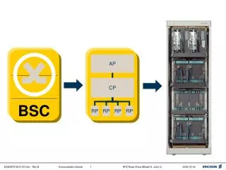
ZXC10-BSC Sub-System. 2004.10.3. Subsystems of BSC. Lesson Objectives: General Study HIRS:High-speed Interconnection Routing Subsystem SVBS:Selector Vocoder Bank Subsystem PCFS:P acket Control Function Subsystem CPS:Call Processing Subsystem

E N D
ZXC10-BSC Sub-System 2004.10.3
Subsystems of BSC Lesson Objectives: General Study HIRS:High-speed Interconnection Routing Subsystem SVBS:Selector Vocoder Bank Subsystem PCFS:Packet Control Function Subsystem CPS:Call Processing Subsystem CDSUS:Channel Data Service Unit Subsystem TS:Timing Subsystem
General Study • BSC working environment requirement Working temperature: 0°C ~+55°C Working humidity: 15%~93% The density of dust in the equipment room with diameters of over 5μm should be ≤3*104 granules/m3. • Power requirement • BSC DC power • 1)Voltage amplitude: The nominal voltage value of the BSC power supplied by the power equipment in the equipment room is -48V. The permitted variation range is -57V~-40V. • 2)The noise level index contained in the DC power voltage should satisfy the requirement in the overall technical specifications by the former MPT. 3)DC power should provide over-voltage
BSC Mechanical Structure--Center Rack HIRS CPS CDSUS TS
BSC Mechanical Structure--Vocoder Rack SVBS or PCFS
Mechanical Features • BSC comprises the central rack and the vocoder rack. • The central rack and the vocoder rack adopts the unified racks and standard plug-in boxes, which provide different functions due to the use of different plug-in unis. • External dimensions of the rack (main body) (H*W*D): 2000 mm*810 mm*600 mm • Outline dimensions of rack (after installation of top shelf and side board) (H×W×D): 2200mm×870mm×600mm • From top to bottom, each rack includes one distribution plug-in box, 3~5 functional plug-in boxes, one fan plug-in box, and dust-proof shelf. There are three types of functional plug-in boxes.
HIRS HIRS Subsystem is switching center and packet data exchange platform of BSC. Functions of HIRS: • Packet data switching • Timing distribution,monitor GPS • Software downloading • Operation and maintenance management on the whole BSS
HIRS Shelf Structure NCM: Network Control Module NIM: Network Interface Module PSMB:Power Supply Module
Input and Output interface RS422 interface Clock interface HIRS Subsystem Operate and maintain interface
NCM NCM is the core module in HIRS shelf • When NCM is in slot 11,it must connect with port 6 of NIM in slot 9 via the internal serial bus on backplane. • When NCM is in slot 12,it must connect with port 6 of NIM in slot 14 via the internal serial bus on backplane. • 2 NCM working mode: active and standby
NCM Functions Major functions of NCM : • Gateway function:data receiving of CO bus and distribution of DIS bus,routing of data frame inside/outside of the local shelf • Distribution of software of respective modules and configuration information; • Fault detection, isolation, report and recovery in HIRS network; • GPS clock distribution; • Serving as the foreground PC of BSM to communicate with the background through 10/100Mbps Ethernet
NCM Panel Indicator&Interface` • Indicator: • RUN:when module normal running,it quick flash • ALM:OFF indicates no fault • ACT:Active/Standby State • Interface: • TEST:Network interface,for debugging but not connected in operations • RS-232:serial port, for debugging but not connected in operations • RST:Manual resetting on boards • M/S:Manual Switching active/standby mode on the foreground
NIM Functions • Receive/send RS-422 serial data • Receive/send data through DISCO • 8+1 redundancy • Clock receiving and distributing • Reports module working states to NCM via I2C bus and accepts NCM control
Node address 0 1 2 3 4 5 6 7 8 9 11 12 13 14 15 10 0 1 2 Port Number N N 3 C C M M 4 5 6 7 Slot No. 2 3 4 5 6 7 8 9 1 0 1 1 1 2 1 3 1 4 1 5 1 6 1 7 1 8 1 9 2 0 2 1 Configuration Direction Configuration Direction NIM Standby Network address distribution
NCM Network Address BSSId = X,SubNetId = 0, NodeId = 7,PortId = 6; CPM Network Address BSSId = X,SubNetId = 0,NodeId = 7,PortId = 7; Network address distribution(Cont.)
8 9 10 11 12 13 14 15 0 1 2 3 4 5 6 7 backup backup N C M N N I I M M NIM daisy chain NIM :8 working + 1 standby and changeover
NIM RUN ALM ACT RST NIM Panel Indicator • RUN: A green indicator, blinking when the board works normally. • ALM: A red indicator, lighting up or blinking in case of board failure. • ACT: A green indicator, lighting up when the board is in master mode. • RST: Reset button.
SVBS--Selector/Vocoder Band Subsystem SVBS is the core part for enabling voice services and supporting SS7 signaling MTP1 and MTP2. • Judge and implement soft handoff: select a path in several soft handoff path by the quality for code type conversion • Code type conversion function: It enables the conversion between 64K PCM codes and variable rate of QCELP codes; • Enables echo cancellation for PCM data on the forward link • Power control • Signaling handle
SVBS Shelf Structure SVICM: Selector Vocoder Interface Control Module SVM: Selector Vocoder Module PSMB:Power Supply Module
Input and Output interface Connected with NIM via RS422 port SVBS Subsystem 4*E1 interfaces connected with MSC
SVICM Functions • S-HIRS:Communicate with HIRS Network • Distribute forward traffic and signaling(SVMSVICM NIM) • Distribute reverse traffic and signaling (SVMSVICM NIM) • Distribute signaling interior SVBS(SVMSVICM ) • Receive and Distribute Clock and TOD message • Manage and control SVM • Signaling handling • Code type conversion between MSC and BSS via DTI
SVBS SVICM 2 I C U gateway C_BUS NIM DIS CO RS422 时钟 SVC SVM1 SVM 7 SVM 8 Clock distribution DTI 4*HW 4*E1 MSC Structure of SVICM
SVICM Panel Indicator • RUN: Running indicator (green), blinking during operation; • ALARM: Alarm indicator (red), lighting up when a software error occurs; • DT0: 1st E1 connection indicator, lighting up to indicate that the E1 link is connects; • DT1: 2nd E1 connection indicator, lighting up to indicate that the E1 link is connects; • DT2: 3rd E1 connection indicator, lighting up to indicate that the E1 link is connects; • DT3: 4th E1 connection indicator, lighting up to indicate that the E1 link is connects; • RST: Reset button.
SVM - Selector & Vocoder Module • transcoding between PCM and QCELP • reverse outer-loop power control • soft handoff • handle layer 3 of Abis interface and layer 2 of IS-95 signaling • assign the timeslot
SVE1 Data Interface SVP SVE2 maintenance bus HW interface clock interface SVE15 Structure of SVM • A SVM contain 1 SVP and 15 SVEs. • SVICM receive traffic data from the RS-422 port of NIM then forward to SVM,SVP forward to SVE,SVE transcoding to PCM and send through HW,in other direction,SVE transcoding PCM to QCELP or EVRC,then send to SVP,then to SVICM,and then NIM.
SVM Panel Indicator • RUN: Running indicator (green), blinking during working normally; • ALARM: Alarm indicator (red), lighting up when a software error occurs; • RESET: Reset button.
PCFS-Packet Control Function Subsystem • Each BSC can support 10 PCFS subsystems. • Each PCFS subsystem comprises 1 PCFIM board and 8 PCF boards. • Each PCFS subsystem is connected with the PDSN via PCFIM board, and provides a 10M/100M self-adaptive physical Ethernet interface through the PCFIM board. • Each PCFS subsystem can carry 4000 PPP connections (Dormant+Active), and 240 activated PPP connections (total number of active ones).
PCFS Functions • To Select a service path with best quality among multiple soft handover paths for data GRE encapsulation. • Enables adaptation between GRE data packets and RLP data packets;. • To establish, configure and maintain A8 and A10 links via A9 and A11 interfaces. • To establish PPP link between MS and PDSN to enable packet data service transmission.
Input and Output Interface • PCFS provides a 10M/100M fast Ethernet interface to be connected with PDSN. • PCFS provides a RS422-port to be connected with HIRS switching network.
CPS-Call Processing Subsystem • CPS is a joint point of BSS system’s resource management and call signaling protocol processing. • CPS comprises two modules:CPM and PAM.
CPS Functions • Handle the signaling of Abis interface • Radio resource maintenance,management and distribution • Trunk resource management • provides A signaling interface. It fulfills A interface startup and re-startup, A interface protective switching, activation of failing data link, control of link labels, and delivery of A messages. • Control over loading of BSS;produce the message of A and ABIS interface:establish the signaling link to CCM and SVICM • Manage the database of BSS,include the parameters of BSS system,ground circuit resource,traffic channel resource,calling record,performances record,handoff record and so on.
NIM 7 port Alarm box RS422 RS485 CPS Subsystem RS485 Connect to power modules of seven racks Input and Output interface of CPS
Hardware feature of CPM According to the software function of CPM,CPM should have the Hardware features below: • CPS sub-system is a joint point of BSS system’s resource management and call signaling protocol processing,processing all the signaling,so the CPM should be powerful. • The CPM is 1+1 hot standby
CPM Panel • RUN:running indication • ALM:error status indication • ACT:green,active status indication • M/S:active/standby switch • RST:reset • TEST1:Ethernet debugging interface
PAM Functions • monitor the running status of the power supply modules in the BSC-side frames and the equipment room environment signals, including temperature, humidity, smoke, and so on. • report the result to the background operation and maintenance console through the NCM for processing; • provides duplex RS232 and RS485 interfaces for the connection of external monitoring devices and alarm box.
CDSUS--Channel Data Service Unit Subsystem Convert signal between RS-422 interface and non-channelized E1,transfer signaling and traffic data between BSC and BTS. BSC-CDSU and BTS-CDSU, have the same hardware structure
RUN ALM DT0 DT1 RST CDSU Panel • RUN Running • ALARM Alarm • DT0 Synchronization A • DT1 Synchronization B • RST Reset Button
ASM ---In CDMA system, BSC communicates with BSC via ASM board to enable inter-BSC soft handoff. The communication link is connected to BSCs via E1 link. ---According to different bandwidth provided by the communication link, ASM board is classified into ASM board providing 2*E1 trunk and ASM board providing 4*E1 trunk.
TS--Timing Subsystem According to the CDMA standard,BSC and BTS independently synchronization the timing signal provided by GPS. Timing subsystem provides such timing signal: • PP2S • 16chips:19.6608MHz • TOD message
TCM Functions TCM board mainly provides the following functions: 1. It receives clock signals of active and standby GPSTMs; 2. It synthesizes and distributes 10MHz signals; 3. It receives 16CHIP and PP2S signals of active and standby GPSTMs; 4. It implements phase-lock on 16CHIP signal; 5. It generates new PP2S.
TCM Panel • RUN green Lights up when the TCM works normally • ALM red Lights up when the TCM works abnormally • LOCK green Lights up when the TCM is locked • CLK: an SMA socket, used for monitoring of the TCM’s 16chip timing signal • PP2S: an SMA socket, used for monitoring of the TCM’s PP2S timing signal and for BS testing
GPSTM Function GPSTM receives 1PPS signal from GPS receiver and generates PP2S signal, 16CHIP signal, 10MHz signal and TOD signal via phase-lock for the usage of the system. In case GPSTM cannot find the satellite, it provides the hold-over function. According to the specifications, the wander of the board should not be over 7ms in 24 hours; in this system, GPSTM implements less than 5ms wander in 4 days. GPSTM also implements active/standby automatic switching. It can detect and report board working states.
GPSTM RUN Run indicator Active/standby indicator ACTIVE GPSAIM Indication of searching for satellite Indication of IPPS phase exceeding 800ns 1PPSAIM Fault indicator AIM Reset key R S T 16CHIP output CLK Power switch PWR RS232 CONTROL