Download
1 / 26
260 likes | 497 Views
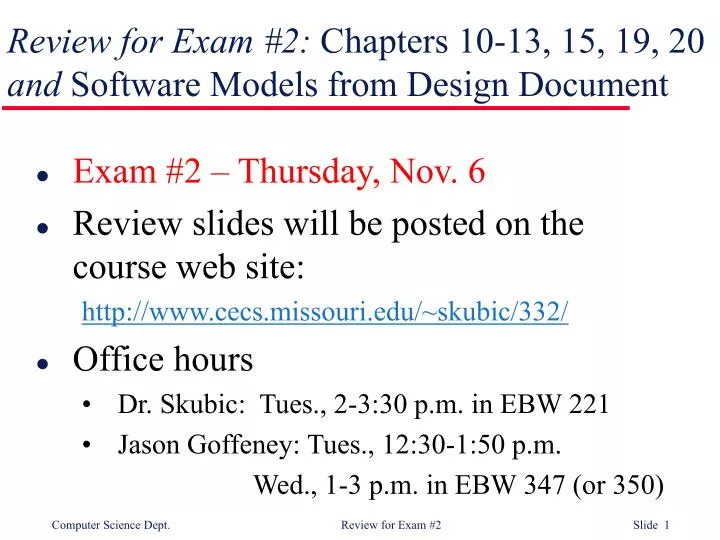
Review for Exam #2: Chapters 10-13, 15, 19, 20 and Software Models from Design Document. Exam #2 – Thursday, Nov. 6 Review slides will be posted on the course web site: http://www.cecs.missouri.edu/~skubic/332/ Office hours Dr. Skubic: Tues., 2-3:30 p.m. in EBW 221

E N D
Review for Exam #2: Chapters 10-13, 15, 19, 20and Software Models from Design Document • Exam #2 – Thursday, Nov. 6 • Review slides will be posted on the course web site: http://www.cecs.missouri.edu/~skubic/332/ • Office hours • Dr. Skubic: Tues., 2-3:30 p.m. in EBW 221 • Jason Goffeney: Tues., 12:30-1:50 p.m. Wed., 1-3 p.m. in EBW 347 (or 350)
Thinking ahead… • Presentations on the Final Project will begin the week before Thanksgiving. • I will post a sign-up sheet outside my office – EBW 221. • Reminder – All of the team members must participate in the final project presentation. • Any problems or questions on the group project?
Chapter 10Architectural Design • System Structuring • Decompose the system into interacting sub-systems block diagram • Repository model – share lots of data • Client-server model – clients request services from servers (distributes the processing) • Control Modeling • Centralized control – one sub-system manages the rest call-return model vs. the manager model • Event-based control – Driven by external events broadcast models vs. interrupt-driven models • Modular Decomposition • Sub-systems are decomposed into modules • Object models vs. Data-flow models The style and structure of the architecture usually depends on both functional and non-functional requirements
Homework #3 Solutions 1. Giving reasons for your answer, suggest an appropriate architectural model for the following systems (Chapter 10): An automated ticket issuing system used by passengers at a railway station. ANSWER: An appropriate model is a centralized model with a shared repository of route and pricing information. Thus, changes are immediately available to all machines. There is not much advantage to a client-server architecture, because little local processing is necessary. The centralized system also allows global information and route use to be collected and processed.
Homework #3 Solutions 1. Giving reasons for your answer, suggest an appropriate architectural model for the following systems (Chapter 10): A computer-controlled video conferencing system which allows video, audio and computer data to be visible to several participants at the same time. ANSWER: An appropriate model here is the client-server model. Local processing will be required here to handle multimedia data.
Chapter 11Distributed Systems Architectures Distributed system software runs on a loosely integrated group of cooperating processors linked by a network. • Multiprocessor architectures • Simplest distributed model – Used for many real-time systems • Client-server architectures • Layers: presentation, application, data management • Fat client vs. thin client vs. 3-tier architecture • Distributed object architectures • Objects may act as producers or users of services – No distinction between clients and servers • Object communication is handled by an object request broker (ORB) • CORBA • An international standard for an ORB (also called middleware)
Homework #3 Solutions 2. What is the fundamental difference between a fat-client and a thin-client approach to client-server systems development? Explain why the use of Java as an implementation language blurs the distinction between these approaches. (Chapter 11) ANSWER:In a fat-client system, some of the application processing is carried out on the client whereas in a thin client system only the user interface is displayed on the client and all of the application processing is carried out on the server. Java blurs the distinction as it allows the development of applets which can be downloaded to the client at execution time. Depending on the functionality of the applet, this allows a degree of control over the processing that is carried out on the client.
Homework #3 Solutions 3. Explain why the use of distributed objects with an object request broker simplifies the implementation of scalable client-server systems. Illustrate your answer with an example. (Chapter 11) ANSWER: The use of distributed objects and an ORB simplifies the implementation of scaleable systems as it is very easy to add additional servers in the form of distributed objects to the system. These can be introduced without perturbing other parts of the system. An example would be a web server which can be easily replicated as the number of users increases.
Chapter 12Object-Oriented Design • Objects and object classes • Relationship between classes and objects • Generalization and inheritance • Advantages and disadvantages • An object-oriented design process • Identify context and use cases • Design the architecture • Identify principal objects • Develop design models, e.g., sequence diagram and statecharts • Specify object interfaces • Design evolution • Information hiding inside objects means changes can be made without unpredictable side-effects
Homework #3 Solutions 4. Explain why adopting an approach to design that is based on loosely coupled objects that hide information about their representation should lead to a design which may be readily modified. (Chapter 12) ANSWER: There are 2 major problems encountered when modifying systems: • Understanding which entities in a program are logically part of some greater entity. • Ensuring that changes do not have unanticipated side-effects (i.e., a change to one entity has an undesirable effect on some other entity).
Homework #3 Solutions, #4 cont. ANSWER: Object-oriented development helps to reduce these problems as it supports the grouping of entities (in classes) so program understanding is simplified. It also provides protection for entities declared within objects so that access from outside the object is controlled (the entity may not be accessible, its name may be accessible but not its representation, or it may be fully accessible). This reduces the probability that changes to one part of the system will have undesirable effects on some other part.
Chapter 13Real-Time Software Design Correct functioning depends on both the results produced and the time at which these results are produced ‘Soft’ real-time vs. ‘Hard’ real-time • Systems design • Identify the stimuli, responses & timing constraints concurrent processes • State machine model State transition diagram • Real-time executives • Real-time clock, interrupt handler, scheduler, dispatcher, resource manager • Monitoring and control systems • Examples – burglar alarm system, temperature controller • Data acquisition systems • Using a ring buffer • Example – reactor flux data collection
Chapter 15User Interface Design Towards a user-centered interface driven by user needs • User interface design principles • User familiarity, consistency, minimal surprise, recoverability, user guidance, user diversity • User interaction • How to provide information from the user to the system • How to present information from the computer system to the user • Styles – direct manipulation, menus, forms, command line, natural language • Information presentation • static vs. dynamic displays • graphical vs. text; analog vs. digital • User support • System help and error messages; user documentation • Interface evaluation • Usability studies; surveys to gather user opinion
Chapter 19Verification and Validation Verification – Are we building the product right? Validation – Are we building the right product? Software inspections vs. software testing • V & V planning • Start early and identify a balance • Software Inspections • Examine the requirements document, design diagrams, code, … • Automated Static Analysis • Parse the code for errors in control flow, use of variables, … • Cleanroom Software Development • Formal specification using a state transition model • Incremental development and structured programming • Static verification and statistical testing
Chapter 20Software Testing • Defect testing • a successful test exposes a previously unknown defect • black-box testing vs. white-box testing (structural testing) • choosing test cases with equivalence partitioning • path testing and cyclomatic complexity (#paths = #edges - #nodes + 2) • Integration testing • tests complete systems or sub-systems • top-down testing vs. bottom-up testing • interface testing • stress testing • Object-oriented testing • test individual classes and clusters of cooperating classes • object integration, e.g., use case or scenario testing • Testing workbenches
REVIEW – Software Models • Requirements • Use Case diagram • Context model • The context diagram • Behavioral model • Data flow diagram (also called process model) • State diagram • Data model • Entity-relationship diagram • Data dictionary • Object models • Hierarchy showing inheritance • Aggregation
Use Case Diagram: factor out common functionality with <<include>>
Use Case Diagram: using a generalization
Context DiagramThe context of an ATM system ATM does NOT include the Account DB, etc.
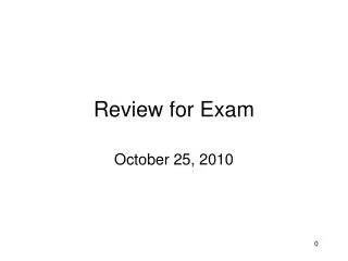
image database medical records system hospital admissions system patient information system drug dispensing system Another Context Diagram from HW#2 Is the Medical Records System part of the Patient Information System?
Data Flow Diagram:Equipment procurement process Also called a Process Model
State Transition DiagramMicrowave oven model Also called a Statechart
Entity-Relationship Diagramhttp://members.iinet.net.au/~lonsdale/docs/erd.pdf Manager Department manages is managed by one to one relationship has works in Employee one to many relationship
Name of object class Class Diagram:Illustrating generation Class attributes Object’s operations