Download
1 / 26
260 likes | 428 Views
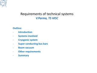
Fessia Paolo, David Smekens and the whole TE-MSC-MDT section. Insulation strategies and materials for incoming SC magnets. Outline . Working conditions Ground Insulation Voltages T echniques Cable insulation Nb -Ti Nb 3 Sn Quench heaters. Conditions of max voltage.

E N D
Fessia Paolo, David Smekens and the whole TE-MSC-MDT section Insulation strategies and materials for incoming SC magnets
Outline • Working conditions • Ground Insulation • Voltages • Techniques • Cable insulation • Nb-Ti • Nb3Sn • Quench heaters
Conditions of max voltage MQXC Nb-Ti 120 mm bore quad voltage increase MQXF Nb3Sn 150 mm bore quad voltage increase The maximum voltage is reached during the quench of the magnet that up to that point was in an He bath (hp. 1.9K). We can assume that we need to be able to insulate the magnet in He gas at 75 K 1 bar (conservative) Courtesy G. Kirby Courtesy E. Todesco
Environment dielectric in function of temperature and pressure 3.5
1000 V Vds 3X1600 V+500 V= 5300 V Vds air= 3.5X Vds= 18550 V 1600 V 1920 V 960 V 2880 V 160 V 3200 V 3520 V
Few Magnet examples I LHC MB MQ MQXC 4-5 layer Polyimide 0.125 mm each minimum overlap 10 mm Creep path >> 12 mm Material: Polyimide foils 0.125 mm thick Number of foils: 4 Minimum number of foils continuous: 2 Minimum overlap 7 mm Creep path >> 7 mm Material: Polyimide foils 0.125 mm thick Number of foils: 4 Minimum number of foils continuous: 2 Minimum overlap 10 mm Creep path >> 10 mm Material: Polyimide foils 0.125 mm thick Number of foils: 4 Minimum number of foils continuous: 2 Minimum overlap 10 mm Creep path >> 10 mm
Specifications the Nb3Sn inter-turn insulation system Do no damage cable during the application Parts to be applied before Nb3Sn reaction shall withstand reaction (typically 650 C for 100 hours) Turn to turn insulation system Voltage withstand level in cryogenic conditions 100-200 V Be of repeatable, constant and controllable thickness Stand High Radiation dose (typical 40-50 MGy with shielding 100 MGy without shielding) Do no deteriorate in cryogenic conditions Mechanically withstand large compression stresses and some bending and shear
If we assume that we have inter-turn voltage in the order of max 100-200 V this could lead to design for about 300 V-600 V cryogenic conditions. In case of needing good insulation also in presence of cracks, this lead to cable distances of about 0.2-0.4 mm.
Standard and reinforced approach Material considerations Possible cable insulation processes evaluated at CERN • Tape • Problems in finding in Europe adequate tape quality for geometry and presence of polyester guiding wires on the edges. No S2 tape found on the Europe market • Problems to achieve good overlapping • Sock type sleeve • Very good results • Problem to find European source • Limited to cable of about 100 m • Direct cable braiding • See following slides
Direct braiding on cable • We have insulated • 10 mm wide cable • 15 mm wide cable • 21 mm wide cable Very promising under all point of view. Only issue, and experienced by us: educate the company to increase Q.C., awareness to avoid and identify possible cable damages that could occur during the braiding
Insulator based approach Braiding of 11 TEX plus MICA Winding of copper coil 11 TEX+ MICA
Yarn for braiding Use standard yarn with organic sizing Use special yarn with temperature stable sizing Use standard yarn with organic sizing for the braiding Braid Thermally or chemically de- size Apply the palmitic acid or other sizing on the yarn AGY 933 S2 glass Braid No carbon residuals No carbon residuals Easy, fast and cheap process Long, complex and costly operation Easy and fast process Carbon residuals after reaction Probable deterioration of fibers during handling without sizing and thermal desizing Average costs
S2 933 temperature behavior Glass fiber after 100 hours at 650C AGY S 2 493 AGY S 2 933 AGY S 2 636 E glass
Metal component belonging to the coilsThese parts (end spacer, winding posts) have to be strongly insulated to the coil and the insulation applied has to withstand reaction. Present practice is to overlap an insulation coating (Plasma Spray Al203) and add an extra protective cloth of fiber glass that will be later impregnated wit the coil R1 R2 R3 R4 R5 R6
Quench Heaters In cryogenic condition withstand V=1.2 (Vq+900 V) Provide very efficient thermal transfer to the coil (typical thickness 0.125 mm or less) Requirement for Q.H. insulation to coil Be robust and allow shaping to follow the coil geometry
Other issues to remind A Nb3Snimpregnated coil has a limited thermal conduction and limited electrical insulation: this leads to problems install effective and electrical safe quench heaters to protect magnets. Quench heaters at the Outer Radius might not be sufficient, as the heat does not immediately penetrate the coil. Inside the bore and inside the inter-layer of the coil, QHs are very technologically challenging. Instrumentation (voltage taps) are also difficult to install as the have to go through the insulation (either VTs installed before reaction, and survive the reaction and potting ; or installed after impregnation by digging into the epoxy to reach the bare conductor). All instrumentation circuit should be tested with the magnet and wire have sufficient voltage insulation rating