Download
1 / 25
310 likes | 591 Views
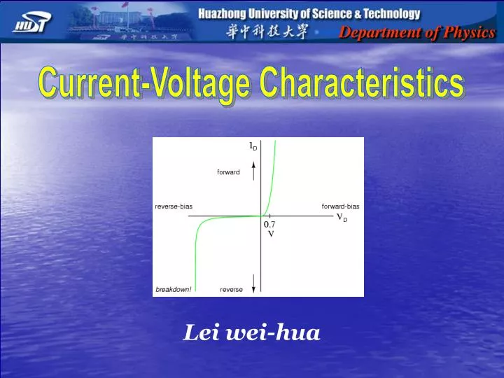
Department of Physics. Current-Voltage Characteristics. Lei wei-hua. Contents. Objectives Pre-lab Questions Introduction & Apparatus Procedure & Experiment Problems. Objectives. Study the current-voltage characteristics of different electrical devices.

E N D
Department of Physics Current-Voltage Characteristics Lei wei-hua
Contents • Objectives • Pre-lab Questions • Introduction & Apparatus • Procedure & Experiment • Problems
Objectives • Study the current-voltage characteristics of different electrical devices • Learn how to use the voltmeter and ammeter
Pre-lab Questions • Sketch the I-V characteristics of resistor, diode and transistor. • What is Ohm’s law? • What are ohmic and nonohmic devices? • What are voltmeter and ammeter?
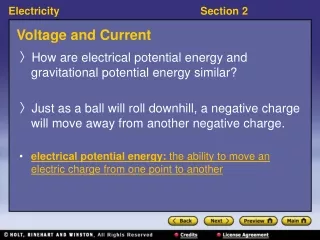
Pre-lab Questions • Sketch the I-V characteristics of resistor, diode and transistor. • The I-V curve of resistor is a straight line. The slope is 1/R. • The I-V curves of diode and transistor are nonlinear and asymmetric.
Pre-lab Questions • What is Ohm’s law? • The resistance remains constant over a wide range of applied voltages or currents. Ohm, a high school teacher in Cologne and later a professor at Munich. Ohm's most important discovery (of 1826) now bears his name: Ohm's Law describes the relationship between voltage, current, and resistance. (The unit of electrical resistance, the ohm, is named after him.). Ohm's importance was not recognized through most of his lifetime, but in 1852 he became professor of physics at the University of Munich. GERG SIMON OHM (1787-1854)
Pre-lab Questions • What are ohmic and nonohmic decvies? • Materials that obey Ohm’s law are said to be ohmic, e.g.. resistor. • Materials whose resistance changes with voltage or current are nonohmic, e.g., diode and transistor. resistor diode transistor
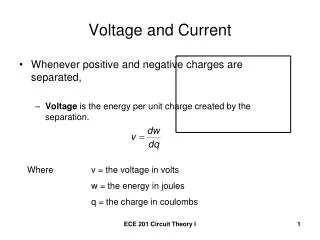
Pre-lab Questions • What are voltmeter and ammeter? voltmeter ammeter • Voltmeters: measure the electrical potential difference between two points in an electric circuit. • Ammeters: measure the electrical current through two points in an electric circuit.
Introduction & Apparatus • The Diode Diode is a typical nonlinear device, it is constructed simply by joining P type and N type silicon At the junction, free electrons from the N-type material fill holes from the P-type material. This creates an insulating layer in the middle of the diode called the depletion zone.
Introduction & Apparatus • How do diodes work When the negative end of the circuit is hooked up to the N-type layer and the positive end is hooked up to P-type layer, electrons and holes start moving and the depletion zone disappears. When the positive end of the circuit is hooked up to the N-type layer and the negative end is hooked up to the P-type layer, free electrons collect on one end of the diode and holes collect on the other. The depletion zone gets bigger.
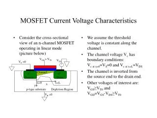
Introduction & Apparatus • The Transistor A transistor is another commonly used nonohmic device. Comparing with diode, it adds a third Silicon part to the diode. These parts are called the “Emitter”, the “Base,” and the “Collector.” PNP transistors and NPN transistors
Introduction & Apparatus • How do transistors work The illustration shows pipework with three openings B, C, and E. The reservoir of water at C is the supply voltage which is prevented from getting though to E by a plunger. If water is poured into B, it pushes up the plunger letting lots of water flow from C to E. If even more water is poured into B, the plunger moves higher, and the flow of water from C to E increases. Therefore, a small input current of electricity to the Base leads to a large flow of electricity from the Collector to the Emitter.
Introduction & Apparatus • The I-V characteristics test box Circuit 1 Resistor Diode Circuit 2 Transistor
Introduction & Apparatus • The I-V characteristics test box (back view) Circuit 1 Circuit 2
Introduction & Apparatus • The meters microammeter voltmeter milliammeter
Procedure & Experiment • CAUTION • Always turn off the power of the box before connecting a circuit. • Always begin by turning the Rw knob to the counter-clockwise stop so that voltage begins at 0V. • Measure the Resistance of Resistor • Measure the I-V Characteristics of Diode • Measure the I-V Characteristics of Transistor (Optional)
Procedure & Experiment • Measure the Resistance of Resistor (Circuit 1) 1. Setting Circuit 1: left panel • Set K2 to left (“Resistor”). • Connect the voltmeter and milliammeter to the test box. Turn the knob on the voltmeter to the 2.5V scale, and the milliammer to 30mA.
Procedure & Experiment • Measure the Resistance of Resistor (Circuit 1) 2. Measure the resistance use Circuit A Circuit A: K1 to left • Turn the “Rw” knob to change voltage. Do 10 measurements
Procedure & Experiment • Measure the Resistance of Resistor (Circuit 1) 2. Measure the resistance use Circuit B Circuit B: K1 to right • Turn the “Rw” knob and do 10 measurements
Procedure & Experiment • Measure the I-V Characteristics of Diode (Circuit 1) 1. Setting Circuit 1: right panel • Set K2 to right (“Diode”).
Procedure & Experiment • Measure the I-V Characteristics of Diode (Circuit 1) 2. Measurement (Forward-biased) Forward-bias: K3 to right • Turn the knob on the voltmeter to the 1V scale, and the milliammeter to 15mA.Turn on the power of the test box. Turn the “Rw” knob to change voltage. Record 10 (V, I) pairs.
Procedure & Experiment • Measure the I-V Characteristics of Diode (Circuit 1) 2. Measurement(Reverse-biased) Reverse-bias: K3 to left • Set K3 to left (“Reverse-bias”). Turn the knob on the voltmeter to the 5V scale, and the milliammeter to 7.5mA, and repeat the above instructions.
Procedure & Experiment • Measure the I-V Characteristics of Transistor (Circuit 2) 1. Setting Circuit 2 • Connect the voltmeter, milliammeter and micro-ammeter to the test box. • Turn the knob on the voltmeter to the 1V scale, the milliammeter to 7.5mA and the microammeter to 100uA.
Procedure & Experiment • Measure the I-V Characteristics of Transistor (Circuit 2) 2. Measurements • Adjust the knob Rw1 to set the base current to 40uA. Turn the “Rw2” knob to change collector voltage. Record 10 (Vce, Ic) pairs. • Set the base current to 60uA, and repeat the above instructions.
Problems • How to determine the anode and cathode of a diode by a multimeter? • Does the Ohm’s law hold for the diode and transistor? Does the diode conduct equally when the current flows in the forward or the reverse directions? End