Download
1 / 11
110 likes | 491 Views
Laser Frequency Stabilization. REU Summer 2006 Margot Phelps Layra Reza Mentor:Dr. Deborah S. Jin. Outline. Using an external cavity diode laser stabilizing the frequency of the laser How lasers are used in the experiment Controlling the laser Interpreting error signals.

E N D
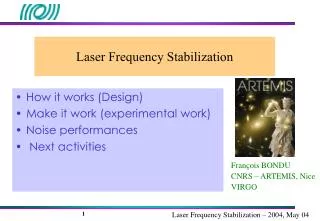
Laser Frequency Stabilization REU Summer 2006 Margot Phelps Layra Reza Mentor:Dr. Deborah S. Jin
Outline • Using an external cavity diode laser • stabilizing the frequency of the laser • How lasers are used in the experiment • Controlling the laser • Interpreting error signals
Building the laser • External cavity diode lasers • Diode wavelength=767 nm. • Here we are collimating the beam.
Threshold curves • Helps characterize the behavior of the laser • The threshold is where the laser begins to lase • Lasing means that the laser is producing a coherent beam, all its photons are in the same quantum state • Important in case of suspected laser failure
Beatnotes Lasers drift in frequency over time. Instantaneously, they are lasing at one frequency, but a time averaged signal shows something different. • Reasons for drift: Electronic noise,Temperature drift,Air flow • Want the laser’s lineshape to be <1MHz
Why is Frequency stabilization important? • Laser imaging needs the laser to be at the right absorption wavelength for the atoms shadow image Zero equals resonant frequency processedimage (shows atom density) • The lineshape of the laser must be >1MHz
Feedback Loops Controlling the laser: A feedback loop or “servo” Frequency Measuring Device laser Laser light Error signal servo Electronicsignal
Saturated Absorption • Widely used setup for laser stabilization • Wide Doppler dip, with extra peaks • Scanning laser frequency to find peaks • saturated absorption peaks at 767 nm for 40K. • sidelocking to reduce frequency drift photodiode output voltage(mV) Frequency(Mhz)
Locking to the Peak Frequency modulation : the wavelength of the laser is scanned across the atomic transition, and the wavelength modulation is seen as varying amplitude modulation. • The ratio of AM to FM versus the laser frequency results in this derivative signal • This signal is at zero when the laser is on resonance • Use this as the error signal for peak locking the laser
The Challenge Saturated absorption lines Sidelock • Pros • Don’t modulate the frequency of the laser itself • Cons • Might be too far away from the resonant frequency Peaklock • Pros • Closer to resonance • Cons • Have to modulate laser frequency Derivative signal We want: A way to combine the sidelock and peaklock to eliminate the drawbacks of both methods
Summary • Importance of laser frequency stabilization • Some widely used methods • Room for improvement: other methods could prove to be better than those in use.