Download
1 / 26
260 likes | 383 Views
By : Johan K ( 26407055 ). Design and Implementation of an Inpainting Application with Interpolation Method. BACKGROUND. Image as a physical property Lots of environment factor s that can affect it’s quality. Will deteriorate as time passes by.

E N D
By : Johan K ( 26407055 ) Design and Implementation of an Inpainting Application with Interpolation Method
BACKGROUND • Image as a physical property • Lots of environment factors that can affect it’s quality. • Will deteriorate as time passes by. • Inpainting as method to refresh the image quality. • The goal of digital inpainting. • The goal of interpolation process.
PROBLEM STATEMENT, SCOPE AND LIMITATIONS • Determine how to mark the area that is designated as input by user as accurate as possible. • Determine how to process the marked area with well step. • Determine how to enable the process to recognize between the input area and the process input. • Implement the interpolation process.
PROBLEM STATEMENT, SCOPE AND LIMITATIONS (Cont.) • User will determine the input area. • The input area will be processed with Interpolation method. • The process will use 3 different methods. • The Output of the process will result in a new image with restored / processed area. • The Application uses BMP or JPEG files as input • The application can save the result image in BMP or JPEG file.
MAIN GOAL • Implement an application, which is able to process a “damaged” image so that it will able to repair the “damaged” area. • Implement an application, which is able to repair the “damaged” area of the image with Interpolation method.
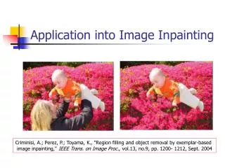
INPAINTING • Inpainting is a method to modify an image in a way that the modification that is done to the image is not able to be recognize easily. • For damaged image, the process involves reconstructing the damaged area to the point where normal people would not able recognize the damage. • Damages usually appeared because of external factors that happened while the image was still physical.
INPAINTING (Cont.) • The digital inpainting is an effort to reconstruct the images to it’s original form as close as possible. • The inpainting techniques are divided based on the purpose, either the full reconstruction of the structure, or just mainly reconstruct the structure. • The differences between the two techniques will differ the time and quality of the output.
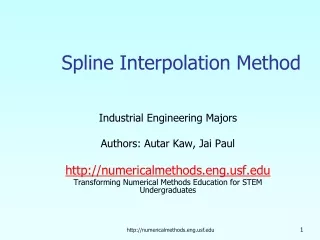
INTERPOLATION • A method to create a new data set based on available data sets that is previously there. • In this particular Inpainting problem, the Interpolation is the method to create or fill the missing RGB color that is inside the input region that User has inputted to an image.
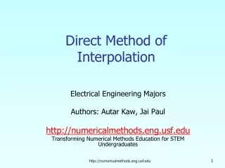
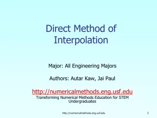
LINEAR INTERPOLATION • A method of interpolation using linear polynomial numbers • Linear interpolates by using two previously known pixels(points) in each of X axis and Y axis dimension. • Compared to other interpolations that is used in this inpainting application, it has risk to produce false value because it only uses up to 4 previously known pixels(points)
LINEAR INTERPOLATION (Cont.) • Y = The desired y value • (x0,y0) = the value of (x,y) in first point • (x1,y1) = the value of (x,y) in second point
BICUBIC INTERPOLATION • A complex version of cubic interpolation which involves in 16 pixels(points) in total to interpolate a new point • Cubic Interpolation itself requires 4 pixels(points) in 1 dimension to interpolate a new point, so basically bicubic interpolation uses 4 cubic in X – axis and interpolate the 4 result in Y axis.
RBF INTERPOLATION • Radial Basis Interpolation utilize Radial Basis Function to determine the weight of each pixel (point) before interpolate them to produce even more accurate value of the new pixel (point). • The weight acted as indicator value to determine the contribution of a certain pixel(point) to the desired new pixel(point). • By determining the weight, the further distance of a pixel to the input process, the lower value it will contribute to determine the new value of a pixel(point)
EXPERIMENT RESULT ON DIFFERENT SIZES OF THE INPUT REGION LINEAR INTERPOLATION MASK 1 +OUTPUT MASK 2 +OUTPUT INPUT MASK 3 +OUTPUT
EXPERIMENT RESULT ON DIFFERENT SIZES OF THE INPUT REGION (Cont.) BICUBIC INTERPOLATION MASK 1 +OUTPUT MASK 2 +OUTPUT INPUT MASK 3 +OUTPUT
EXPERIMENT RESULT ON DIFFERENT SIZES OF THE INPUT REGION (Cont.) RBF INTERPOLATION MASK 1 +OUTPUT MASK 2 +OUTPUT INPUT MASK 3 +OUTPUT
EXPERIMENT RESULT ON UNDAMAGED IMAGE EXPERIMENT ON LARGE AREA LINEAR RESULT INPUT BICUBIC RESULT MASK RBF RESULT
EXPERIMENT RESULT ON UNDAMAGED IMAGE (Cont.) EXPERIMENT ON NARROW AREA LINEAR RESULT INPUT BICUBIC RESULT MASK RBF RESULT
EXPERIMENT RESULT ON IMAGES WITH COLOR GRADATION LINEAR INTERPOLATION INPUT MASK 1 +OUTPUT MASK 2 +OUTPUT
EXPERIMENT RESULT ON IMAGES WITH COLOR GRADATION BICUBIC INTERPOLATION INPUT MASK 1 +OUTPUT MASK 2 +OUTPUT
EXPERIMENT RESULT ON IMAGES WITH COLOR GRADATION RBF INTERPOLATION INPUT MASK 1 +OUTPUT MASK 2 +OUTPUT
CONCLUSION • The Size of the Input Region determines greatly of the result because it counts how many pixels needed to be calculated as accurately as possible. • All of the Interpolation method failed to preserve the color edge as well as the shape of an object. • By processing undamaged images, it visually proves that the Interpolation is able to fill the damaged area accurately. • Gradation Images can be successfully repaired depend on the info given by the area of input, this also proves that, user should marked the input area with the info around the input area as accurate as possible.
SUGGESTION • Provide image tools to edit the image(or) input area in a way that the object can still be maintained without sacrificing them in the interpolation process. • Provide zoom function to the image so that marking of the input area can be done even more accurately. • Input of this application can be another type of digital images, not just JPEGs or BMPs. • Application can be developed further more with another interpolation method in use, or even consider using other method that emphasize on preserving the texture and edge of the image.
End of Presentation • Thank you for your attention