Download
1 / 32
320 likes | 331 Views
Hubble Space Telescope Servicing Mission Four (HST SM4): Unique Challenges for STS-125. Bob Dedalis, HST Payload Safety Manager Miranda Cooter, HST Lead Flight Safety Engineer Patrick Mitchell, Payload Safety Review Panel Executive Secretary William Hill, HST Lead Ground Safety Engineer

E N D
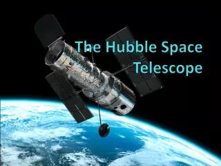
Hubble Space Telescope Servicing Mission Four (HST SM4):Unique Challenges for STS-125 Bob Dedalis, HST Payload Safety Manager Miranda Cooter, HST Lead Flight Safety Engineer Patrick Mitchell, Payload Safety Review Panel Executive Secretary William Hill, HST Lead Ground Safety Engineer Phillip Adkins, Systems Safety Engineer
Introduction • Mission Overview • SM4 first time in seven years HST serviced • Nominal design called for once every 3 years • More new hardware than any previous mission • SIC&DH added very late • First time since Columbia a shuttle was not used for ISS construction
Payload Bay Equipment • Four Full Equipment Carriers • Included a servicing platform Science Instrument Control and Data Handling Unit Flight Support System pivots and rotates to enable in-bay servicing
Safety Review Phase I PDR Safety Review Phase II CDR Safety Review Phase III Delivery Safety Review Phase 0 Design Concept Flight Safety Verification Tracking Log Track Verification of Items To Be Conducted After Phase III Review Payload Organization Approval NSTS Review Hazard Report Identify Hazard Controls Payload Organization Concurrence NSTS Concurrence Hazard Report Verify Design Implement Controls Payload Organization Concurrence NSTS Concurrence Hazard Report Verify Hardware As Built Implement Controls Payload Organization Concurrence NSTS Concurrence Preliminary Hazard Reports Identification of Hazards Payload Safety Review Process Update Only Update Only For Each Hazard
Hazard Identification Process Postulate Failure (PHA/FMEA/FTA) Change Design NSTS Requirements Not Approved System/ Sub-system/Interfaces Hazard to Crew/STS Requirements Met Write HR Perform Hazard Assessment Yes Critical No No Yes (Generic Hazard) Catastrophic Confirm Fault Tolerance or DFMR in Design/Operations No Hazard Write HR Review with JSC Approved 2 Fault-Tolerant 1 Fault-Tolerant Write HR Redesign Verify Controls *ARHR (Accepted Risk Hazard Report): New to the PSRP documentation process for SM4. Method for Shuttle program to accept the risk of safety non-compliant conditions ARHR * Document for CoFR 12/20/2019
Safety Challenges • Soft Capture Mechanism (SCM) • Batteries • Late addition of Science Instrument Control and Data Handler (SIC&DH) • Complex on-orbit Repairs • STIS • Advanced Camera for Surveys (ACS) • Lack of Shuttle Safe-Haven • Increased chance of on-orbit debris
Soft Capture Mechanism and Battery Isolation Switch Miranda Cooter
Soft Capture Mechanism • Designed to enable controlled de-orbit • HST originally designed to be returned in payload bay • HST does not have propulsion system • Installed onto Aft Shroud • Flew on FSS between HST and FSS support ring • Was risk of connecting HST to FSS via SCM (inability to close shuttle payload bay doors) • Systems Safety participated in initial design • Performed Initiating Event Tree Analysis • Insured that each major function included crew-activated override
Soft Capture Mechanism Berthing Latch outside SCM attach mechanisms Servicing Platform Soft Capture Mechanism Berthing Latches and SCM Attach Points Crew-Activated Remote Drive Soft Capture Mechanism Detail on Next Slide
SCM Mechanism Detail Radial Out View Radial In View HST Release Override HST Attach Override FSS Release Override FSS Override Assy FSS Attach Override Sill Plate Adapter
Final SCM Fault Tolerance • Separated Mission Success issues from Safety concerns • Mission Success is single fault tolerant • Flight Safety must be dual fault tolerant
Batteries • Launched charged • 88 amp-hour batteries • Nickel Hydrogen • Battery Isolation Switch (BIS) Installed • COTS product • Based on military headlight switch • Not designed to be fail-safe • Barrier Analysis applied Battery Isolation Switches (BIS)
Modifications to BIS • BIS Not Fail-safe • Failure causes switch to be closed (i.e. ON) • Identified as a safety issue • Conducted Hazard Analysis • No Backaway prevention on handle • Possibility of Whiskers • Cadmium and Zinc coatings • Potential for “hot” handle if internal failure • Not visually identifiable to crew • Hazard process improved design • Staked handle fastener to prevent backaway • Detailed analysis of potential for whiskers • Found whiskers in non-flight version of BIS • Through analysis & test, determined that, for this design, whiskers cannot sustain arc • Added non-conductive paint to handles
IMAX Accommodations and Science Instrument Control and Data Handling Phillip Adkins
Steps to Certify IMAX • Previous IMAX flights reviewed with new analysis/testing done as needed • Proof Pressure Testing • Vibration • Functional Test • Thermal Vacuum Test • New Carrier Electrical Harness • IMAX presented as a separate reflown payload
Late Addition of SIC&DH • Reduced time for final certification • Six month certification cycle • Flight safety closely integrated with design and development to insure success • Safety documentation available from unit certifications
EVA Safety Considerations Bill Hill
Extra-Vehicular Activities (EVA) • Included instrument and equipment exchange • Done on each previous servicing mission • New techniques and tools developed for on-orbit, in situ repairs of instrument • Highly complex operations • Required specially designed tools to enable delicate repairs to circuit boards tailored to crew needs • Flight safety engineers participated in tool development beginning with design
EVA Timeline • Five long days of EVA with four astronauts participating
Tool Development Process • Tools Developed and designed with crew and safety participation • Design and development includes full review and verification
Shuttle Specific Challenges Patrick Mitchell
Shuttle-Specific Safety Challenges • ISS was not available for Safe-Haven • Launch-on-need (LON) shuttle processed and available for rescue • Enhanced Micro-Meteorite On-orbit Debris (MMOD) Risk • Shuttle flew protected attitudes when HST specific operations permitted • Shuttle inspections performed • Tile inspections performed before and after servicing • Insures no damage during ascent or from MMOD
Solutions Applied • Safety Systems Analysis Techniques Used • Initiating Event Tree Analysis (IETA) • Barrier Analyses • Fault Tolerance Analyses • JSC Safety Requirements and Processes • Safety engineer integration into hardware design teams resulted in safe hardware by design Successful application of System Safety techniques contributed to a successful Servicing Mission