Download
1 / 33
340 likes | 362 Views
THREE DIMENSIONAL EQUILIBRIUM OF RIGID BODIES. If forces acting on a rigid body are three dimensional, six equations of equilibrium can be used:. At most six unknowns can be determined in three dimensional rigid body equilibrium problems.

E N D
If forces acting on a rigid body are three dimensional, six equations of equilibrium can be used:
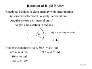
At most six unknowns can be determined in three dimensional rigid body equilibrium problems. These unknowns will generally involve support / bearing reactions and tension forces in ropes, wires, etc. In general, employing the moment equation first may facilitate the solution of the problem. Moment can either be taken about a point where the number of unknown values is maximum, or it can be taken about an axis / line, where the lines of action of unknown forces intersect.
Representation of Support Reactions in ThreeDimensional Problems
T String, Rope, Chain, Cord, Belt
Contact with Smooth Surface or Ball Support
Roller Support or Wheel on Rail (Makaralı Mesnet veya Ray Üzerinde Tekerlek)
Ball-and-Socket Joint (Küresel Mafsal)
Sliding Support (Kayar mesnet)
Built-in / Fixed / Cantilever Support (Ankastre Mesnet)
Double Hinge (Çift Menteşe) If hinges are supporting forces along the hinge axis, force reactions will occur along hinge axis (In case of double hinge no moment reactions occur!)
Single Hinge (Tek Menteşe) Couple reactions perpendicular to hinge axis due to imbalance, depending on design, may also exert force along the z axis.
Radial / Journal /Ball Bearing (Tek Radyal Yatak) Couple reactions perpendicular to bearing axis due to imbalance!
Double Radial / Journal / Ball Bearings Çift Radyal Yatak (Bilyeli Yatak) No moment reaction occurs in double radial bearings!
Single Bearing (Thrust-Bearing) Tek Basma Yatağı (Konik Yatak) Force reactions in three directions + moment reactions in two dimensions (perpendicular to the bearing axis)
Thrust Bearing (Basma Yatağı) and Radial Bearing (Radyal Yatak)
1. The 9 m steel boom has a mass of 600 kg with center of mass at midlength. It is supported by a ball and socket joint at A and the two cables under tensions T1 and T2. The cable which supports the 2000 kg load leads through a sheave (pulley) at B and is secured to the vertical x-y plane at F. Calculate the magnitude of the tension T1.
2. The shaft, lever and handle are welded together and constitute a single rigid body. Their combined mass is 28 kg with mass center at G. The assembly is mounted in bearings A and B, and rotation is prevented by link CD. Determine the forces exerted on the shaft by bearings A and B while the 30 N.m couple is applied to the handle as shown.
60 mm 240 mm 250 mm 220 N y 225 mm 120 mm B 160 mm G E A C z D x 3. The lever AB is welded to the bent rod BCD which is supported by bearing E and cable DG. Assuming that the bearing can exert an axial thrust and couples about axes parallel to the x and z axes, determinethe tension in cable DG and the reaction at E under the action of the 220 N force. The mass of ABCD is neglected.
4. The shaft assembly (consisting of welded pieces AB, ED and CD) is supported by a thrust bearing at A and a radial bearing at B. The assembly is subjected to a force at C and a couple . If it is known that the y component of the reaction at bearing B is (N), determine the vector expressions of the force , couple and the bearing reactions at A and B. Link ED lies in the yz plane. ED=250 mm.
By Bz Ax Ay Az
5. Under the action of the 40 N·m torque applied to the vertical shaft, the restraining cable AC limits the rotation of the arm OA and attached shaft to an angle of 60° measured from the y axis. The collar D fastened to the shaft prevents downward motion of the shaft in its bearing. Calculate the bending moment M, the compression P and the shear force V in the shaft at section B. (Bending moment, expressed as a vector, is normal to the shaft axis and shear force is also normal to the shaft axis.)
T B By My Mx Bx Bz
y 150 mm 100 mm 50 mm z 25 mm 150 N T 90 mm x 300 mm 25 mm 6. For the portion of a machine shown, the 100 mm diameter pulley A and wheel B are fixed to a shaft supported by bearings at C and D. The spring of constant 360 N/m is unstretched when q=0°and the bearing at C does not exert any axial force. Knowing that q=120° and the machine is at rest and in equilibrium, determine the tension T and the reactions at C and D. Neglect the weights of the shaft, pulley and wheel.
50 cm 50 cm 40 cm 15 cm 15 cm 25 cm 7. Two rods are welded to form a T-shaped structure. The end D of the structure rests against a frictionless vertical wall, while ends A and B are supported by radial bearings. When a 600 N magnitude vertical force P is applied to the midpoint E of the part DC of the structure, determine the reactions at D.
8. A 450 mm long uniform rod AB has a weight of 304 N and is attached to a ball-and-socket joint at A. Theend B of the rod rests against an inclined frictionless surface and is held in the equilibrium position shown by cord BC. Knowing that cord BC is 450 mm long, determine the tension in the cordand the reactions at A and B.
x z y 9. The 25 kg rectangular access door is held in the 90° open position by the single prop CD. Determine the force Fin the prop and the magnitude of the force normal to the hinge axis AB in each of the small hinges A and B.
x Ax Ay Az Bx G Bz By z y FCD W=25(9.81) N