Download
1 / 42
470 likes | 588 Views
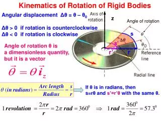
Chapter 15. Kinematics of Rigid Bodies. translation:. - rectilinear translation. - curvilinear translation. rotation about a fixed axis. general plane motion. motion about a fixed point. Introduction.

E N D
Chapter 15 Kinematics of Rigid Bodies
translation: • - rectilinear translation • - curvilinear translation • rotation about a fixed axis • general plane motion • motion about a fixed point Introduction • Kinematics of rigid bodies: relations between time and the positions, velocities, and accelerations of the particles forming a rigid body. • Classification of rigid body motions: • general motion
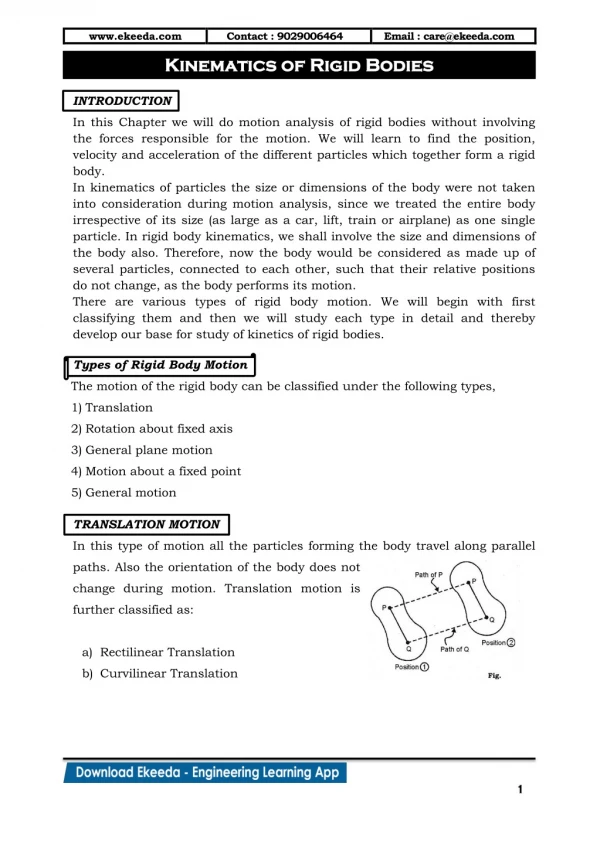
Consider rigid body in translation: • direction of any straight line inside the body is constant, • all particles forming the body move in parallel lines. • For any two particles in the body, • Differentiating with respect to time, All particles have the same velocity. • Differentiating with respect to time again, All particles have the same acceleration. Translation
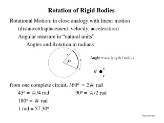
Velocity vector of the particle P is tangent to the path with magnitude • The same result is obtained from Rotation About a Fixed Axis. Velocity • Consider rotation of rigid body about a fixed axis AA’
Differentiating to determine the acceleration, • Acceleration of P is combination of two vectors, Rotation About a Fixed Axis. Acceleration
Velocity of any point P of the slab, • Acceleration of any point P of the slab, • Resolving the acceleration into tangential and normal components, Rotation About a Fixed Axis. Representative Slab • Consider the motion of a representative slab in a plane perpendicular to the axis of rotation.
Recall • Uniform Rotation, a = 0: • Uniformly Accelerated Rotation, a = constant: Equations Defining the Rotation of a Rigid Body About a Fixed Axis • Motion of a rigid body rotating around a fixed axis is often specified by the type of angular acceleration.
Displacement of particles A and B to A2and B2 can be divided into two parts: • translation to A2and • rotation of about A2 to B2 General Plane Motion • General plane motion is neither a translation nor a rotation. • General plane motion can be considered as the sum of a translation and rotation.
Absolute and Relative Velocity in Plane Motion • Any plane motion can be replaced by a translation of an arbitrary reference point A and a simultaneous rotation about A.
Assuming that the velocity vA of end A is known, wish to determine the velocity vB of end B and the angular velocity w in terms of vA, l, and q. • The direction of vB and vB/A are known. Complete the velocity diagram. v v A A = = q cos w v l B A v A w = q l cos Absolute and Relative Velocity in Plane Motion
Absolute and Relative Velocity in Plane Motion • Selecting point B as the reference point and solving for the velocity vA of end A and the angular velocity w leads to an equivalent velocity triangle. • vA/B has the same magnitude but opposite sense of vB/A. The sense of the relative velocity is dependent on the choice of reference point. • Angular velocity w of the rod in its rotation about B is the same as its rotation about A. Angular velocity is not dependent on the choice of reference point.
SOLUTION: • Will determine the absolute velocity of point D with • The velocity is obtained from the given crank rotation data. • The directions of the absolute velocity and the relative velocity are deter-mined from the problem geometry. • The unknowns in the vector expression are the velocity magnitudeswhich may be determined from the corresponding vector triangle. • The angular velocity of the connecting rod is calculated from Sample Problem 15.3 The crank AB has a constant clockwise angular velocity of 2000 rpm. For the crank position indicated, determine (a) the angular velocity of the connecting rod BD, and (b) the velocity of the piston P.
SOLUTION: (Graphical Method) • Will determine the absolute velocity of point D with • The velocity is obtained from the crank rotation data. • The direction of the absolute velocity is horizontal. The direction of the relative velocity is perpendicular to BD. Compute the angle between the horizontal and the connecting rod from the law of sines. Sample Problem 15.3 7.6 cm The velocity direction is as shown.
Determine the velocity magnitudes from the vector triangle. Sample Problem 15.3 vB =1591.44 cm/s
Sample Problem 15.3 Solution (Vector Method)
Plane motion of all particles in a slab can always be replaced by the translation of an arbitrary point A and a rotation about A with an angular velocity that is independent of the choice of A. • The same translational and rotational velocities at A are obtained by allowing the slab to rotate with the same angular velocity about the point C on a perpendicular to the velocity at A. Instantaneous Center of Rotation in Plane Motion • The velocity of all other particles in the slab are the same as originally defined since the angular velocity and translational velocity at A are equivalent. • As far as the velocities are concerned, the slab seems to rotate about the instantaneous center of rotation C.
If the velocity at two points A and B are known, the instantaneous center of rotation lies at the intersection of the perpendiculars to the velocity vectors through A and B . • If the velocity vectors at A and B are perpendicular to the line AB, the instantaneous center of rotation lies at the intersection of the line AB with the line joining the extremities of the velocity vectors at A and B. Instantaneous Center of Rotation in Plane Motion • If the velocity vectors are parallel, the instantaneous center of rotation is at infinity and the angular velocity is zero. • If the velocity magnitudes are equal, the instantaneous center of rotation is at infinity and the angular velocity is zero.
The instantaneous center of rotation lies at the intersection of the perpendiculars to the velocity vectors through A and B . • The trace of the locus of the center of rotation on the body is the body centrode and in space is the space centrode. Instantaneous Center of Rotation in Plane Motion • The velocities of all particles on the rod are as if they were rotated about C. • The particle at the center of rotation has zero velocity. • The particle coinciding with the center of rotation changes with time and the acceleration of the particle at the instantaneous center of rotation is not zero. • The acceleration of the particles in the slab cannot be determined as if the slab were simply rotating about C.
Sample Problem 15.5 • SOLUTION: • Determine the velocity at B from the given crank rotation data. • The direction of the velocity vectors at B and D are known. The instantaneous center of rotation is at the intersection of the perpendiculars to the velocities through B and D. The crank AB has a constant clockwise angular velocity of 2000 rpm. For the crank position indicated, determine (a) the angular velocity of the connecting rod BD, and (b) the velocity of the piston P. • Determine the angular velocity about the center of rotation based on the velocity at B. • Calculate the velocity at D based on its rotation about the instantaneous center of rotation.
Calculate the velocity at D based on its rotation about the instantaneous center of rotation. Sample Problem 15.5 • SOLUTION: • From Sample Problem 15.3, • The instantaneous center of rotation is at the intersection of the perpendiculars to the velocities through B and D. • Determine the angular velocity about the center of rotation based on the velocity at B.
Absolute acceleration of a particle of the slab, • Relative acceleration associated with rotation about A includes tangential and normal components, Absolute and Relative Acceleration in Plane Motion
Givendetermine • Vector result depends on sense of and the relative magnitudes of Absolute and Relative Acceleration in Plane Motion • Must also know angular velocity w.
Write in terms of the two component equations, x components: y components: Absolute and Relative Acceleration in Plane Motion • Solve for aBand a.
SOLUTION: • The angular acceleration of the connecting rod BD and the acceleration of point D will be determined from • The directions of the accelerations are determined from the geometry. Sample Problem 15.7 • The acceleration of B is determined from the given rotation speed of AB. Crank AG of the engine system has a constant clockwise angular velocity of 2000 rpm. For the crank position shown, determine the angular acceleration of the connecting rod BD and the acceleration of point D. • Component equations for acceleration of point D are solved simultaneously for acceleration of D and angular acceleration of the connecting rod.
SOLUTION: • The angular acceleration of the connecting rod BD and the acceleration of point D will be determined from Sample Problem 15.7 • The acceleration of B is determined from the given rotation speed of AB. 7.6 cm
SOLUTION: • The angular velocities are determined by simultaneously solving the component equations for • The angular accelerations are determined by simultaneously solving the component equations for Sample Problem 15.8 In the position shown, crank AB has a constant angular velocity w1 = 20 rad/s counterclockwise. Determine the angular velocities and angular accelerations of the connecting rod BD and crank DE.
x components: y components: Sample Problem 15.8 • SOLUTION: • The angular velocities are determined by simultaneously solving the component equations for
x components: y components: Sample Problem 15.8 • The angular accelerations are determined by simultaneously solving the component equations for
Problem 1 ก้าน AB หมุนรอบจุด A ด้วยความเร็วรอบคงที่ 900 rpm ในทิศทางตามเข็มนาฬิกา จงหาความเร่งของจุด P เมื่อ = 60o
Problem 1 • ขั้นตอนการแก้ปัญหา • 1. หาเวคเตอร์ระบุตำแหน่ง • 2. หาความเร็ว และความเร็วเชิงมุม • 3. หาความเร่ง • 4. หาเวคเตอร์ระบุตำแหน่ง • 5. หาความเร็ว และความเร็วเชิงมุม • 6. หาความเร่ง
Problem 1 • ขั้นตอนที่ 1 : หาเวคเตอร์ระบุตำแหน่ง • ขั้นตอนที่ 2 : หาความเร็ว
Problem 1 • ขั้นตอนที่ 3 : หาความเร่ง
Problem 1 • ขั้นตอนที่ 4 : หาเวคเตอร์ระบุตำแหน่ง
Problem 1 • ขั้นตอนที่ 5 : หาความเร็ว และความเร็วเชิงมุม
Problem 1 • ขั้นตอนที่ 6 : หาความเร่ง
Problem 2 • กลไกดังรูปถูกใช้ในเครื่องยนต์ของเรือดำน้ำ ซึ่งประกอบด้วยก้านเดี่ยว AB ก้านต่อ BC และ BD จงหาความเร็วของจุด C ที่ตำแหน่งดังรูป โดยก้าน AB หมุนด้วยความเร็วเชิงมุมคงที่ 5 rad/s ในทิศทางตามเข็มนาฬิกา
Problem 3 • จากชุดกลไกที่แสดงดังรูป กำหนดให้ก้าน AB เคลื่อนที่ในทิศทางหมุนตามเข็มนาฬิกา ด้วยความเร็วเชิงมุมคงที่ 6 rad/s จงหาความเร่งของจุด D
Problem 4 • ก้าน BD ยาว 300 mm และก้าน AB หมุนด้วยความเร็วรอบคงที่ 300 rpm ในทิศทางทวนเข็มนาฬิกา จงหาความเร่งของจุด D เมื่อ = 90o