Download
1 / 8
80 likes | 207 Views
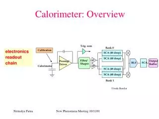
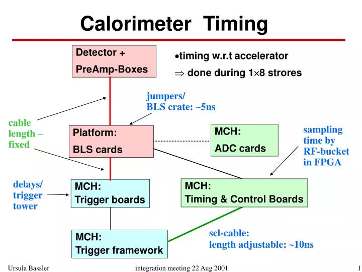
Calorimeter Timing. Detector + PreAmp-Boxes. timing w.r.t accelerator done during 18 strores. jumpers/ BLS crate: ~5ns. cable length – fixed. sampling time by RF-bucket in FPGA. MCH: ADC cards. Platform: BLS cards. delays/ trigger tower. MCH: Timing & Control Boards.

E N D
Calorimeter Timing Detector + PreAmp-Boxes • timing w.r.t accelerator • done during 18 strores jumpers/ BLS crate: ~5ns cable length – fixed sampling time by RF-bucket in FPGA MCH: ADC cards Platform: BLS cards delays/ trigger tower MCH: Timing & Control Boards MCH: Trigger boards scl-cable: length adjustable: ~10ns MCH: Trigger framework
Cal Timing: L1 timing • Verification of cable between from Detector to Trigger Summers (BLS-boards): CC uniform ECN, ECS: different regions • cable from trigger summers to trigger receiver boards (MCH): 3 different lengths (ECN, CC, ECS) – same as in Run I • finer adjustment for different EC regions • adjustment possible for each trigger tower with delay line em
Trigger/Read Out timing flash ADC Read Out adjusted to peak of the Trigger Pickoff measurements done for a sample of em/had channels in CC same value used everywhere • systematic adjustment comparing L1Cal-Read Out by varying the Trigger by +/- 1 RF-bucket • final L1Cal trigger Read Out needed
signal time -1 0 +1 Timing Studies: triple sampling Triple sampling runs: comparison of energy measured at the nominal position, 132ns earlier/later • ratios allow to determine time offset • more precise timing from comparison with Spice model
type A preamp. type B preamp. type D preamp. type E preamp. Timing: Model Validation Model validation: comparing pulser calibration signal with Spice Model Measurement Simulation em Model optimisation: pulse reflexion measurements on the detector had • verification underway
Timing: cryostat comparison ECN CC early/ nominal late/ nominal ECS after 1st adjustment from scope measurements: 3 cryostats and all crates show essential the same behavior !
Timing Studies: delay scan + 97 ns + 113 ns + 81 ns =0.64 =0.61 =0.39 =0.69 early/ nominal =1.04 =0.82 =0.77 =0.78 late/ nominal at first look an offset of 113 ns seems correct
Status & Outlook • yesterday: new FPGA code, with 6 RF-buckets shift (113 ns) • analysis of triple sampling data underway • Spice Model validation • extraction of time-offset from comparison with Spice Model • separation of measurement with different PreAmp Types • Fine Adjustment for each Quadrant • October shutdown(?): fine adjustment for each BLS crate? • Trigger/Precision Read-Out comparisons a.s.a.p