Download
1 / 14
140 likes | 261 Views
Mathematical model of fencer’s hand. Dainis Dzenushko Student, SPb State Polytechnical University, Faculty for Physics and Mechanics, Department for Theoretical Mechanics. Task.

E N D
Mathematicalmodelof fencer’s hand DainisDzenushko Student, SPb State PolytechnicalUniversity, Faculty for Physics and Mechanics, Department for Theoretical Mechanics
Task Create mathematical model, that finds the position of a hand and comes to this position from any previous position with visualization on C# language, using given parameters (changes of angles in joints and coordinates of a shoulder)
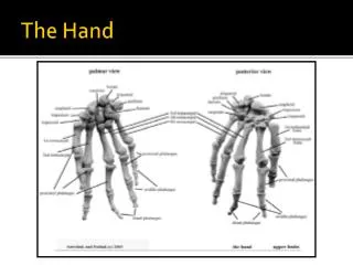
Degrees of freedom This model has 9 degrees of freedom:2 — translationmovement of a shoulder (front/back; up/down)3 — shoulder jointas a ball joint1 — elbow joint1 — rotation of wrist round it’saxis2 — wrist(2 perpendicular cylindrical joints)
Hand rotation Rotation of hand parts is realized by the rotation of corresponding vector round the corresponding axis. This is realized by scalar multiplication of rotation tensor and this vector. The rotation tensor which iscalculated using following formula: After that it is needed to rotate other vectors and corresponding basis’ that are farther from shoulder than considered one. It is also done by scalar multiplication with the same rotation tensor. By the same way the rotation of all 3 vectors on needed angles is done. Then we calculate new coordinates of joints.
Realization of rotation For visualization of rotation we have to know the positions of hand between initial and next positions. So the problem is that the rotation tensors are not additive. Then we don’t rotate hand on additional angles from each new position, instead of this we rotate hand on bigger angles on every step from initial position.
Realization inMATLAB Using the MATLAB this algorithm of rotation was realized in order to calculate path of hand movement and check this algorithm. The examples of such paths are shown below.
Structure of program interface in C# The program interface is based on tabs (TabControl). And consists of two layers: outer(Graph, Tools, Settings, About) and sub-layer for Settings tab: (Color Settings, Graph Settings) Then we will consider on all this tabs.
Graph tab • This tab contains visualization of ongoing position of a hand and has functional: camera rotation and Zoom. • In this tab works following keys: • Up/Down – rotation round the horizontal axis • Left/Right– rotation round the vertical axis • Ctrl + Up/Down/Left/Right – faster rotations • +/- (OemPlus/OemMinus)– isZoom
Settings tab This tab is responsible for setting displaying parameters of hand model. It contains two sub-tabs. The first one(Color Settings) allows to set color and transparency of model. Second one(Graph Settings) allows to set quality of displayed model. Also it allows to set coefficients of camera rotation and camera zoom.
Program realization of 3D-graphics Program interface is created by using special library WPF (Windows Presentation Foundation) and built-in XAML redactor in Microsoft Visual Studio. What is WPF: “The Windows Presentation Foundation is Microsoft’s next generation UI framework to create applications with a rich user experience. It is part of the .NET framework 3.0 and higher. WPF combines application UIs, 2D graphics, 3D graphics, documents and multimedia into one single framework. Its vector based rendering engine uses hardware acceleration of modern graphic cards. This makes the UI faster, scalable and resolution independent.”
Viewport3D element Graphics contents in 3-DWPFapplication is encapsulated in Viewport3D element, which can be placed on two-dimensional element such as program window. Graphics system identifiesViewport3Das two-dimensional visual element such as many in WPF. Viewport3Dfunction as preview window of three-dimensional scene.More precisely it is projection of 3-D scene on plane (screen).
Drawing 3-D objects Drawing of objects is realized by triangulation, that means that we need to build it of triangles. We will notice that back side of triangles is transparent as default.
Using high-speed camera In order to capture the way fencer fights was used high-speed camera. It was used because using only human eyes it is not able to see in details what is happening, what fencer does. By the way mainly fencer have to implement movements on high speed and he can not do it slower.
Results • The ongoing results of this project: • The simple model that moves hand from one point to another is implemented in MATLAB. • MATLAB model was optimized selecting the closest way to new position • The program interface containing main functionality is written in C# • Videos of fencer’s movements prepared using high-speed camera • What is going to be done: • Rewriting operating part from MATLAB to C# program • Usage of limitations in joints • Creating of database of kinds of movement using videos from high-speed camera