Download
1 / 10
230 likes | 604 Views
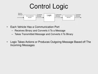
Motor Control PLCs and Ladder Logic. An Introduction. Hard-wired Motor Control Circuitry. Thermal protection not shown. Manufacturers wiring diagram. Definitions - PLC.

E N D
BAE 3023 Motor ControlPLCs and Ladder Logic An Introduction
Hard-wired Motor Control Circuitry BAE 3023 Thermal protection not shown
Manufacturers wiring diagram BAE 3023
Definitions - PLC BAE 3023 • PLC: (Programmable Logic Controller) An industrial control device developed to accept contact closure inputs and to provide outputs that drive relay coils. • The device may be re-programmed with code relating inputs to outputs • Modern PLCs may allow analog input/output and may support high level language functions (C, C++, BASIC) • Programming logic includes simple logic, timing functions counting functions, sequences, and may include complex algorithms (eg. PID) • Examples: Allen-Bradley, Schneider-Modicon, GE, Moeller, etc.
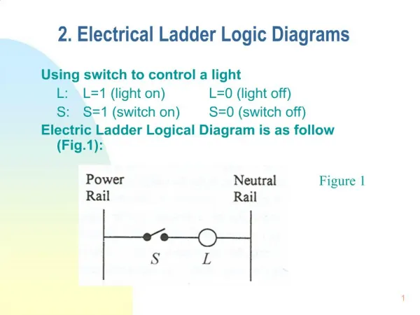
Definitions - Ladder Logic BAE 3023 • Ladder Logic: Graphical language for describing output of an electrical switching system as a function of its inputs. • Also known as “relay ladder logic” or RLL • Commonly used in PLC coding • Primarily used to relate logical inputs (switch closures) to relay coil outputs. (Start switch used to energize a motor contactor relay) • Commonly used to document control equipment in process plants • Example:
Motor Control Ladder Logic BAE 3023 • Note: • Power circuit is not shown, only control wiring • Left side ladder is source, right is sink • Many rungs or “circuits” can be shown
Allen-Bradley Pico PLC BAE 3023 • Circuit elements • “I” Input contact closures • “Q” Output contact closures (drives coil) • “T” Timer device • “C” Counter device • “M” Auxillary relay • “H” Time of day • “A” Analog input • “D” Display on screen • “R”,”S” Expansion devices
Demonstration BAE 3023 • Picosoft Demonstrator
Time Delay BAE 3023 • Time delayed start of conveyor with All STOP
stop and start delay BAE 3023 • Time delayed start and time delayed stop