Download
1 / 18
180 likes | 293 Views
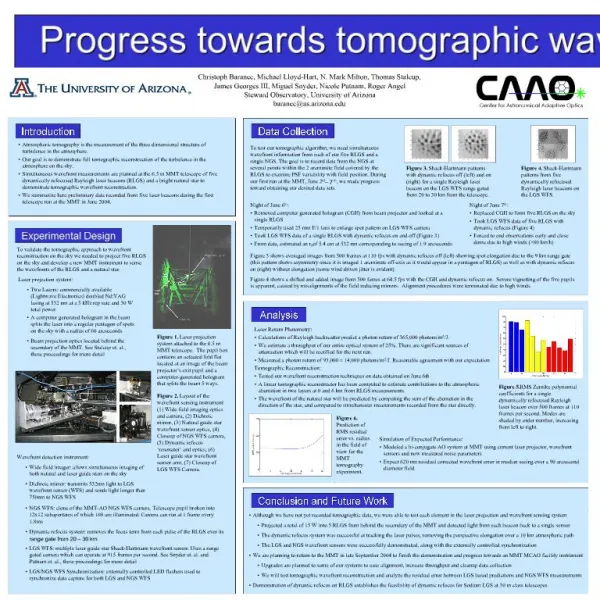
Center for Astronomical Adaptive Optics Steward Observatory, The University of Arizona. C. Baranec, M. Lloyd-Hart, N. M. Milton T. Stalcup, M. Snyder, & R. Angel. Tomographic reconstruction of stellar wavefronts from multiple laser guide stars. MMT Science Symposium, June 2006.

E N D
Center for Astronomical Adaptive Optics Steward Observatory, The University of Arizona • C. Baranec, M. Lloyd-Hart, N. M. Milton • T. Stalcup, M. Snyder, & R. Angel Tomographic reconstruction of stellar wavefronts from multiple laser guide stars • MMT Science Symposium, June 2006 Image courtesy Gabor Furesz
Tomography - Introduction • Atmospheric tomography is the measurement of the three dimensional structure of turbulence in the atmosphere. • Accomplished by measuring the integrated wavefront aberration from multiple probes, either stars or artificially generated laser beacons. • The integrated wavefront distortion along any line of sight contained by the beacons can be calculated. • When using LGS as probes and a single deformable mirror (DM) to correct for a single line of sight is known as laser tomography adaptive optics (LTAO) • In contrast to our previous studies of simple ground layer AO (GLAO) where the beacon signals are averaged to get an estimate of ground layer turbulence which leads to improved seeing over large, 2+ arcminute, fields.
Tomography at the MMT • We have deployed a five beacon Rayleigh laser guide star (RLGS) source at the MMT to test ground layer and tomographic reconstruction of atmospheric turbulence. • Multi-laser wavefront sensing has been chosen as the baseline for GMT, and the technology needs to be tested. • Development of a competitive LGS AO system at the MMT which can support the current and future suite of AO instruments. • Switched from a prototype to a facility instrument at the beginning of 2006. On sky this past April. Intend to close the AO loop around LGS measurements in the fall. • Here, I present our system and first results of open loop tomographic adaptive optics at the MMT.
Wavefront Sensor (WFS) Instrument mounts to MMT Cassegrain focus. Three cameras run simultaneously. RLGS WFS: Multiple laser guide star Shack-Hartmann wavefront sensor. Hexapolar geometry, breaks pupil into 36 or 60 subapertures. Uses a range gated Lincoln Labs CCID18 chip. Dynamic refocus system removes the focus term from each pulse of the RLGS over its range gate from 20 – 29 km NGS WFS: Optical clone of the MMT-AO NGS WFS camera with an E2V CCD39. Pupil broken into 12x12 subapertures of which 108 are illuminated. Sensor on translation slide, to allow exploration of field in one axis. Wide Field Tilt Sensor: 2.5 arcminute field, measures image motion of all stars within field Prototype WFS Instrument RLGS WFS NGS WFS Tilt Sensor
New Facility WFS Instrument • Facility Wavefront Sensor Instrument mounts to MMT Cassegrain focus. Mounts all current and future AO instruments to underside of WFS Instrument in the same way as with the MMT’s NGS AO system. • RLGS WFS: • Same design transferred from prototype instrument. • NGS WFS: • Clone of current MMT NGS AO system. • Field steering mirror to give larger 2 arcminute diameter field. • Single Star Tilt Sensor: • Standard CCD57, looking into upgrading to APD’s. • Same 2 arcminute field as NGS WFS • Variable beam splitter between NGS WFS and Tilt Sensor • Limiting magnitude V=16 at 200 fps
Improvement in LGS WFS September 2004 June 2005 April 2006 50 fps 36 subapertures Defective CCD 50-100 fps 60 subapertures New CCD 200 fps 60 subapertures
Atmospheric Parameters • During our runs, able to collect information about atmospheric parameters at the MMT site, Mt. Hopkins, AZ. • Estimated height of ground layer by estimating θ0gl from single beacon correction of NGS at different separations and relating them through equation (Hardy 1998): • hg = 380m (Sept 2004) • hg = 530m (June 2005) • Joint estimation of r0 and L0* (at λ = 500 nm): • June 2005 • r0 = 13 - 26 cm, L0 = 13 - 30 m with mean 19 m • April 2006 (limited data so far) • r0 = 18 - 23 cm, L0 = 13.5 to 27 m *formal method developed by F. Chassat (dissertaton 1992)
Wavefront Reconstruction • Wavefront reconstruction of the laser beacons and the ground truth natural star: • RLGS wavefront reconstruction by inversion of synthetic influence matrix of Zernike modes on our geometry of Shack-Hartmann pattern. • NGS wavefront reconstruction by using the same reconstructor matrix as used in the closed-loop MMT NGS AO system. The NGS WFS is optically the same, so we can use the same reconstructor. • Stellar tilt measurements made from image motion off of wide field tilt camera. • GLAO estimates based on simple average of LGS reconstructed wavefronts.
Tomographic Reconstruction • Tomographic reconstruction assumes linear relation between LGS and NGS wavefronts: • For each ith set of simultaneous wavefront measurements, âi is an estimate of NGS zernike coefficients, bi are the measured LGS zernike coefficients and tilt measurements of field stars, and T is the tomographic reconstructor. • We derive T by a direct inversion of the data using singular value decomposition (SVD). T is given by: • Where B is constructed from ~3000 data vectors b, and inverted with SVD to give B-1. A is constructed from the corresponding vectors a.
Tomographic Reconstruction Camera Data: NGS Tilt Sensor LGS Reconstructed Wavefronts: Tomographic Estimate Individual Beacons NGS
GLAO vs. Tomography Example of GLAO vs. Tomography in tracking Zernike mode Defocus (Dashed Blue) NGS ground truth, (Sold Black) LGS Estimate
Residual RMS after correction RMS residuals over Zernike orders 2 through 8 for nine separate 60 second data sets Seeing conditions: r0 = 13 – 22 cm L0 = 12 – 25 m Example of RMS residual wavefront error after GLAO and LTAO correction
April 2006 Results June 2005 Uncorrected: 511 nm GLAO Residual: 360 nm Tomographic Residual: 259 nm (single tilt star) Tomographic Residual: 243 nm (3 field tilt stars) April 2006 Uncorrected: 395 nm GLAO Residual: 277 nm Tomographic Residual: 157 nm (single tilt star) *Fitting error on LGS WFS geometry: ~130 nm
Simulated PSFs Simulated K-band PSFs using recorded wavefront information from Zernike orders 1 through 8 Real time images at 50 fps with simulated turbulence up to Zernike order 30 60 s exposures with simulated turbulence up to Zernike order 100 Uncorrected GLAO LTAO FWHM (arcseconds)
Future Work • Prepare system for closed loop operation in GLAO mode Fall ’06. • Characterize system, analyze actual performance using J H K imager PISCES at 0.027”/pixel plate scale. • Further analysis on optimal tomographic reconstructors • Start science program • Build new 4 arcminute field 4Kx4K GLAO NIR camera
Conclusion • What we have learned about multi laser wavefront sensing at the MMT: • Our new facility WFS Instrument is continually improving in throughput and optical alignment . • MMT site has good seeing characteristics. • Able to demonstrate in open loop LTAO techniques. • The residual RMS stellar wavefront aberration after GLAO and LTAO correction is constant in time, over a range of atmospheric conditions. • This correction useful into J H and K bands.