Download
1 / 1
10 likes | 114 Views
The Development of the Bunch Length Detector (BLD) KIM Joon Yeon , KIM Do Gyun , BHANG Hyoung Chan, KIM Jong Won 1 , YUN Chong Cheoul 2 Seoul National University, Department of Physics & Astronomy. 1 National Cancer Center. 2 Chung-Ang University. ABSTRACT.

E N D
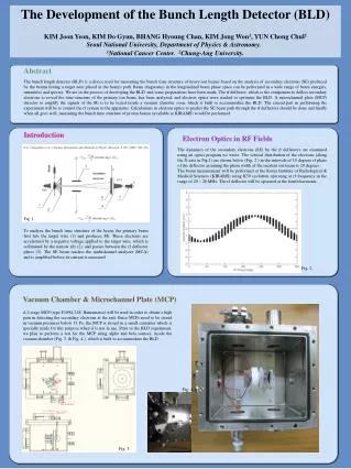
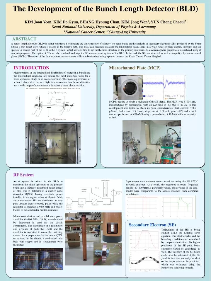
The Development of the Bunch Length Detector (BLD) KIM JoonYeon, KIM Do Gyun, BHANG Hyoung Chan, KIM Jong Won1, YUN Chong Cheoul2Seoul National University, Department of Physics & Astronomy. 1National Cancer Center. 2Chung-Ang University. ABSTRACT A bunch length detector (BLD) is being constructed to measure the time structure of a heavy-ion beam based on the analysis of secondary electrons (SEs) produced by the beam hitting a thin target wire, which is placed in the beam’s path. The BLD can precisely measure the longitudinal beam shape in a wide range of beam energy, intensity and ion species. A crucial part of the BLD is the rf system, which deflects SEs to reveal the time-structure of the primary ion beam. Its electromagnetic properties are analyzed using rf analysis programs. The optics of SEs are also resolved to design the SE measurement system of the BLD. In the end, the SEs are detected as well as amplified by microchannel plates (MCPs). The result of the time structure measurements will soon be obtained using a proton beam at the Korea Cancer Center Hospital. INTRODUCTION Microchannel Plate (MCP) Measurements of the longitudinal distribution of charge in a bunch and the longitudinal emittance are among the most important tools for a beam dynamics study or an accelerator tune. The main requirements of a bunch shape detector are: high time resolution, low beam distortion and a wide range of measurements in primary beam characteristics. MCP is needed to obtain a high gain of the SE signal. The MCP (type F1094-21s, manufactured by Hamamatsu, with an L/d ratio of 40) that is in use in this development was tested to check its basic characteristics (dark current: ≤ 0.5 pA/cm2; dark count: ≤ 3 /s∙cm2; strip current: 0.08 mA; gain: ~106) and a brief test was performed at KIRAMS using a proton beam of 40 MeV with an intensity of 1nA. RF System S-parameter measurements were carried out using the HP 8753C network analyzer. As a result, the measured resonant frequency ranges (80~100MHz), s-parameter values, and q-values of the cold-model were comparable to the values obtained from computer simulations. An rf system is critical in the BLD to transform the phase spectrum of the primary beam into a spatially distributed bunch image of SEs. The rf deflector is a quarter wave resonator (QWR) having electrode plates installed in the region where rf electric fields are a maximum. SEs are distributed as they pass through these electrode plates while the resonator is operated at 92.9 MHz and phase-locked to the accelerator master oscillator. Mini-circuit devices and a solid state power amplifier (1~100 MHz, 50 W, manufactured by Empower) is used for the circuit components. The knowledge of s-parameters and q-values of both the QWR and the amplifier is important to create the matching circuit. As a preparation for the actual QWR to be used in the circuit, a cold-model was built with copper and its s-parameters were measured. Secondary Electron (SE) Trajectories of the SEs is being studied using the Lorentz force equation. The electric fields and the boundary conditions are calculated by computer simulations. For higher precisions of the SE path, beam emittance would be considered as well. The intensity of the SE beam could also be estimated if the SE yield for fast ions normally incident on the target wire can be predicted, which was estimated using the Rutherford scattering formula.