Download
1 / 1
10 likes | 145 Views
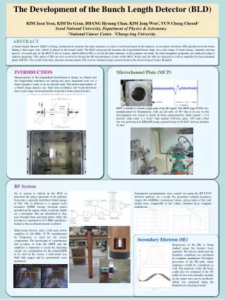
The Development of the Bunch Length Detector (BLD) KIM Joon Yeon , KIM Do Gyun , BHANG Hyoung Chan, KIM Jong Won 1 , YUN Chong Chul 2 Seoul National University, Department of Physics & Astronomy. 1 National Cancer Center. 2 Chung-Ang University. Abstract.

E N D
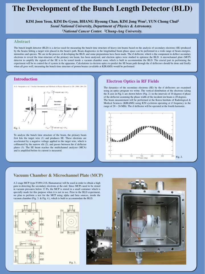
The Development of the Bunch Length Detector (BLD) KIM JoonYeon, KIM Do Gyun, BHANG Hyoung Chan, KIM Jong Won1, YUN Chong Chul2Seoul National University, Department of Physics & Astronomy. 1National Cancer Center. 2Chung-Ang University. Abstract The bunch length detector (BLD) is a device used for measuring the bunch time structure of heavy-ion beams based on the analysis of secondary electrons (SE) produced by the beams hitting a target wire placed in the beam's path. Beam diagnostics in the longitudinal beam phase space can be performed in a wide range of beam energies, intensities and species. We are in the process of developing the BLD, and some preparations have been made. The rf deflector, which is the component to deflect secondary electrons to reveal the time-structure of the primary ion beam, has been analyzed, and electron optics were studied to optimize the BLD. A microchannel plate (MCP) detector to amplify the signals of the SE is to be tested inside a vacuum chamber soon, which is built to accommodate the BLD. The crucial part in performing the experiment will be to control the rf system in the apparatus. Calculations in electron optics to predict the SE beam path through the rf deflectors should be done and finally when all goes well, measuring the bunch time structure of proton beams (available at KIRAMS) would be performed. Introduction Electron Optics in RF Fields The dynamics of the secondary electrons (SE) by the rf deflectors are examined using an optics program we wrote. The vertical distribution of the electrons (along the X-axis in Fig.1) are shown below (Fig. 2.) in the intervals of 10 degrees rf phase of the deflector assuming the phase width of the incident ion beam is 20 degrees. The beam measurement will be performed at the Korea Institute of Radiological & Medical Sciences (KIRAMS) using K50 cyclotron operating at rf frequency in the range of 20 ~ 26 MHz. The rf deflector will be operated at the fourth harmonic. Fig. 1. To analyze the bunch time structure of the beam, the primary beam first hits the target wire (1) and produces SE. These electrons are accelerated by a negative voltage applied to the target wire, which is collimated by the narrow slit (2), and passes between the rf deflector plates (3). The SE beam reaches the multichannel analyzer (MCA) and is amplified before its current is measured. Fig. 2. Vacuum Chamber & Microchannel Plate (MCP) A 2-stage MCP (type F1094-21S, Hamamatsu) will be used in order to obtain a high gain in detecting the secondary electrons at the end. Since MCPs need to be stored in vacuum pressures below 13 Pa, the MCP is stored in a small container which is specially made for this purpose when it is not in use. Prior to the BLD experiment, we plan to perform a test for the MCP using alpha and beta sources, inside the vacuum chamber (Fig. 3. & Fig. 4.), which is built to accommodate the BLD. Fig. 4. Fig. 3.