Download
1 / 23
250 likes | 331 Views
Readout Processing and Noise Elimination Firmware for the Fermilab Beam Loss Monitor System. Wu, Jinyuan C. Drennan, R. Thurman-Keup, Z. Shi, A. Baumbaugh and J. Lewis Fermilab, April 2007. RAM. Ion Chamber Input. CIC Sums. De-ripple Process. ADC 21 m s/sample. Immediate Sliding Sum.

E N D
Readout Processing and Noise Elimination Firmware for the Fermilab Beam Loss Monitor System Wu, Jinyuan C. Drennan, R. Thurman-Keup, Z. Shi, A. Baumbaugh and J. Lewis Fermilab, April 2007
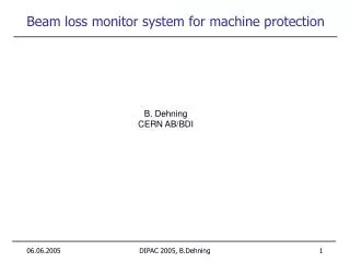
RAM Ion Chamber Input CIC Sums De-ripple Process ADC 21ms/sample Immediate Sliding Sum A>B Threshold I Fast Sliding Sum A>B Threshold F Slow Sliding Sum A>B Threshold S Very Slow Sliding Sum A>B Threshold V Abort Logic Seq128 The Digitizer Card for the Fermilab Beam Loss Monitor System • Beam loss input signals from ion chambers are integrated and digitized. • Sliding sums are accumulated and compared with pre-loaded thresholds. • Over threshold in several places causes beam abort based on pre-defined setting. • Beam loss signals are filtered and “de-rippled” for display purposes. • Sequence is controlled by “Seq128” block.
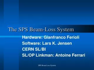
ADC 21ms/sample The Problem: 3F 60Hz AC Time Domain Frequency Domain • Rectify noise from power supply using 3-phase 60Hz AC are picked up by the input cable laying in the accelerator tunnel.
Filter Functions 21ms/sample 124 samples Sliding Sum Cascaded Integrator Comb (CIC) Sum of 2nd Order First Zero @ 360 Hz • The CIC sum is a sliding sum of sliding sums. • The frequency response of CIC sum is a sinc2(x) function that has 2nd order zeros and better stop band suppression. Frequency
Signals Filtering Works, But Partially Sliding Sum CIC Sum • Noises >360Hz, the dominating portion, are filtered out in both filter functions. • CIC sum is a lot smoother than the sliding sum. • But small signals are still buried under ripples of 60 and 180 Hz.
Ramping Why Not Filtering Further? • Filtering is an averaging process over many periods. There is not much time after reset. • The noises before the accelerator ramping and after have different amplitudes and shapes. • A “De-Ripple” algorithm has been developed.
De-ripple Process (1.1)Waveform Extraction, Storage and Validation • The CIC sum is stored into the waveform buffer and accumulated for the waveform mean. Waveform Buffer Page 0 S Waveform Mean Waveform Buffer Page 1 S Waveform Mean
De-ripple Process (1.2)Waveform Extraction, Storage and Validation • When it shows a good periodic property, the waveform becomes valid. Waveform Buffer Page 0 S Waveform Mean Waveform Buffer Page 1 S Waveform Mean
De-ripple Process (1.3)Waveform Extraction, Storage and Validation • If the data is non-periodic, the waveform becomes invalid. Waveform Buffer Page 0 S Waveform Mean Waveform Buffer Page 1 S Waveform Mean
De-ripple Process (2)Waveform Subtraction The De-rippled Sum Waveform Buffer Page 0 - - S Waveform Mean Waveform Buffer Page 1 The waveform mean is subtracted to preserve DC component in the final result. S Waveform Mean
Results of De-ripple Process • Those otherwise hard-to-see small signals now become visible. • DC and very slow signals are also preserved.
x[n] x[n] -x[n-K] S + s[n] s[n] Filter Implementation Recursive != IIR Finite Impulse Respond (FIR) Infinite Impulse Respond (IIR) Non-Recursive Implementation Yes NO Resource Friendly Recursive Implementation Possible Yes Sliding Sum The non-recursive implementation needs: • 124 memory fetches, • 124 additions and • more ops for longer sum lengths. The recursive implementation needs: • 1 memory fetch, • 2 add/sub operations • regardless sum length.
x[n] x[n] -x[n-K] + -2x[n-K] + x[n-2K] s[n] u[n] x[n] -s[n-K] + + y[n] y[n] *h1 *h2 S *h[K] y[n] Recursive Implementation of CIC Sum CIC Sum The non-recursive implementation needs: • 248 memory fetches, • 248 multiplications, • 248 additions and more ops for longer sum lengths. The CIC sum constructed as a sliding sum of sliding sums: • 2 memory fetches, • 0 multiplications, • 4 add/sub ops for any sum length. The re-formulated CIC sum uses the raw data buffer rather than a separate buffer.
Process Sequencing CH0 Sum1 Sum2 Sum3 Sum4 CIC1 CIC2 WF E,S,V WF SUB Sum1 Sum2 Sum3 Sum4 CIC1 CIC2 WF E,S,V WF SUB CH1 Sum1 Sum2 Sum3 Sum4 CIC1 CIC2 WF E,S,V WF SUB CH2 Sum1 Sum2 Sum3 Sum4 CIC1 CIC2 WF E,S,V WF SUB CH3 • Flat design is fast but uses a lot of logic elements. • Sequencing the process saves logic elements significantly. • Partially flat and partially sequence design sometimes is a better arrangement in FPGA. CH0 CH1 Sum1 Sum2 Sum3 Sum4 CIC1 CIC2 WF E,S,V WF SUB Sum1 Sum2 Sum3 Sum4 CIC1 CIC2 WF E,S,V WF SUB Sum1 Sum2 Sum3 Sum4 CIC1 CIC2 WF E,S,V WF SUB Sum1 Sum2 Sum3 Sum4 CIC1 CIC2 WF E,S,V WF SUB CH2 CH3
+ Sliding Sum 4 Sliding Sum 2 Sliding Sum 3 (-) + Sliding Sum 1 (-) x[n] x[n-L] -2x[n-K] -2x[n-L-K] + + x[n-2K] x[n-L-2K] u[n] u[n-L] + + y[n] MaxDY y[n-L] Decimation Counter If |y[n]-y[n-L]|>MaxDY for entire period, then PG++. WF PG=0 S WF PG=1 S PG - - WF-WM DR=y[n]-(WF-WM) - BLM DC Process Sequencing Fully Sequencing Partially Flat • The processes of calculating sliding sums and CIC sums are fully sequenced. • The de-ripple processor is flat for the process path. But it operates sequentially for 4 channels.
Conditional Branch Logic Reset A Program Counter ROM 128x 36bits Control Signals CLK Loop & Return Logic + Stack ELMS– Enclosed Loop Micro-Sequencer Allows jump back as in microprocessors Special in ELMS Supports FOR loops at machine code level • PC+ROM is a good sequencer in FPGA. • Adding Conditional Branch Logic allows the program to loop back. • Loop & Return Logic + Stack is a special feature in ELMS that supports FOR loops at machine code level. PC Control Signals Opration 00 000000000000000 01 001000100011010 LD R1, #n 02 000010001000000 LD R2, #addr_a 03 000000000000100 LD R3, #addr_X 04 000000010001000 LD R7, #0 05 000000000100001 BckA1 LD R4, (R2) 06 000100000010000 INC R2 07 000001000100000 LD R5, (R3) 08 000100010000001 INC R3 09 001001000100000 MUL R6, R4, R5 0a 000000010001000 EndA1 ADD R7, R7, R6 0b 000010000010000 DEC R1 0c 000000100000100 BRNZ BckA1
desA RTN CondJMP JMPIF JMP ROM 128x 36bits 0x04 RUNat04 cnt EndA BckA PC Reset +1 bckA endA Compare LoopBack CNT LoopBack = DEC = (PC==endA) && (CNT!=0) Loop & Return Registers + Stack (128 words) DEC LastPass LastPass = (PC==endA) && (CNT==1) RTN Push Pop FOR BckA1 EndA1 #n LD R2, #addr_a LD R3, #addr_X LD R7, #0 BckA1 LD R4, (R2) INC R2 LD R5, (R3) INC R3 MUL R6, R4, R5 EndA1 ADD R7, R7, R6 LD R8, R7 ELMS – Detailed Block Diagram User Control Signals The Stack supports nested loops, up to 128 layers.
What’s Good About ELMSFOR Loops at Machine Code Level Microprocessor The ELMS LD R1, #n LD R2, #addr_a LD R3, #addr_X LD R7, #0 BckA1 LD R4, (R2) INC R2 LD R5, (R3) INC R3 MUL R6, R4, R5 EndA1 ADD R7, R7, R6 DEC R1 BRNZ BckA1 FOR BckA1 EndA1 #n LD R2, #addr_a LD R3, #addr_X LD R7, #0 BckA1 LD R4, (R2) INC R2 LD R5, (R3) INC R3 MUL R6, R4, R5 EndA1 ADD R7, R7, R6 Conditional Branch 25% • Looping sequence is known in this example before entering the loop. • Regular micro-processor treat the sequence as unknown. • ELMS supports FOR loops with pre-defined iterations at machine code level. • Execution time is saved and micro-complexities (branch penalty, pipeline bubble, etc.) associated with conditional branches are avoided.
Conclusion • The de-ripple algorithm is an useful alternative method for eliminating low frequency periodic noises. • The ELMS is a handy sequence controller in FPGA that uses small amount of resources.
The End Thanks
What’s Good about ELMSNo ALU => Small Resource Usage Princeton Architecture Harvard Architecture Fermilab Architecture(?) Program DATA Memory Program Control Program Memory Program Control Program Memory Sequencer (ELMS) ALU ALU DATA Memory DATA Memory Data Processor • The Princeton Architecture is more suitable at system level while Harvard Architecture is better suited at micro-structure level. • Regular microprocessors cannot run looped program without an ALU. • The ALU takes large amount of resource while may not be efficiently utilized for data processing tasks in FPGA. • The ELMS can run nested loop program without an ALU. • Further separation of Program and data is therefore possible. • The ELMS is kept small.