Download
1 / 28
810 likes | 2.28k Views
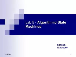
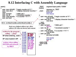
ECE 448 Lecture 9. Algorithmic State Machine (ASM) Charts. Required reading. P. Chu, FPGA Prototyping by VHDL Examples Chapter 5, FSM. S. Brown and Z. Vranesic , Fundamentals of Digital Logic with VHDL Design Chapter 8.10, Algorithmic State Machine (ASM) Charts.

E N D
ECE 448 Lecture 9 Algorithmic State Machine (ASM) Charts ECE 448 – FPGA and ASIC Design with VHDL
Required reading • P. Chu, FPGA Prototyping by VHDL Examples • Chapter 5, FSM • S. Brown and Z. Vranesic, Fundamentals of Digital Logic with VHDL Design • Chapter 8.10, Algorithmic State Machine • (ASM) Charts ECE 448 – FPGA and ASIC Design with VHDL
Algorithmic State Machine (ASM) Charts ECE 448 – FPGA and ASIC Design with VHDL
Algorithmic State Machine Algorithmic State Machine – representation of a Finite State Machine suitable for FSMs with a larger number of inputs and outputs compared to FSMs expressed using state diagrams and state tables. ECE 448 – FPGA and ASIC Design with VHDL
Elements used in ASM charts (1) State name Output signals 0 (False) 1 (True) Condition or actions expression (Moore type) (a) State box (b) Decision box Conditional outputs or actions (Mealy type) (c) Conditional output box ECE 448 – FPGA and ASIC Design with VHDL
State Box • State box – represents a state. • Equivalent to a node in a state diagram or a row in a state table. • Contains register transfer actions or output signals • Moore-type outputs are listed inside of the box. • It is customary to write only the name of the signal that has to be asserted in the given state, e.g., z instead of z<=1. • Also, it might be useful to write an action to be taken, e.g., count <= count + 1, and only later translate it to asserting a control signal that causes a given action to take place (e.g., enable signal of a counter). State name Output signals or actions (Moore type) ECE 448 – FPGA and ASIC Design with VHDL
Decision Box • Decision box – indicates that a given condition is to be tested and the exit path is to be chosen accordingly The condition expression may include one or more inputs to the FSM. 0 (False) 1 (True) Condition expression ECE 448 – FPGA and ASIC Design with VHDL
Conditional Output Box • Conditional output box • Denotes output signals that are of the Mealy type. • The condition that determines whether such outputs are generated is specified in the decision box. Conditional outputs or actions (Mealy type) ECE 448 – FPGA and ASIC Design with VHDL
ASMs representing simple FSMs • Algorithmic state machines can model both Mealy and Moore Finite State Machines • They can also model machines that are of the mixed type ECE 448 – FPGA and ASIC Design with VHDL
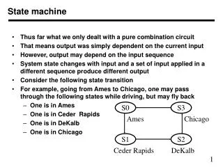
Reset w = 1 ¤ ¤ A z = 0 B z = 0 w = 0 w = 0 w = 1 w = 0 ¤ C z = 1 w = 1 Moore FSM – Example 2: State diagram ECE 448 – FPGA and ASIC Design with VHDL
Next state Present Output z state w = 0 w = 1 A A B 0 B A C 0 C A C 1 Moore FSM – Example 2: State table ECE 448 – FPGA and ASIC Design with VHDL
ASM Chart for Moore FSM – Example 2 ECE 448 – FPGA and ASIC Design with VHDL
Example 2: VHDL code (1) USE ieee.std_logic_1164.all ; ENTITY simple IS PORT ( clock : IN STD_LOGIC ; resetn : IN STD_LOGIC ; w : IN STD_LOGIC ; z : OUT STD_LOGIC ) ; END simple ; ARCHITECTURE Behavior OF simple IS TYPE State_type IS (A, B, C) ; SIGNAL y : State_type ; BEGIN PROCESS ( resetn, clock ) BEGIN IF resetn = '0' THEN y <= A ; ELSIF (Clock'EVENT AND Clock = '1') THEN ECE 448 – FPGA and ASIC Design with VHDL
Example 2: VHDL code (2) CASE y IS WHEN A => IF w = '0' THEN y <= A ; ELSE y <= B ; END IF ; WHEN B => IF w = '0' THEN y <= A ; ELSE y <= C ; END IF ; WHEN C => IF w = '0' THEN y <= A ; ELSE y <= C ; END IF ; END CASE ; ECE 448 – FPGA and ASIC Design with VHDL
Example 2: VHDL code (3) END IF ; END PROCESS ; z <= '1' WHEN y = C ELSE '0' ; END Behavior ; ECE 448 – FPGA and ASIC Design with VHDL
Reset ¤ w = 1 z = 0 ¤ ¤ w = 0 z = 0 w = 1 z = 1 A B ¤ w = 0 z = 0 Mealy FSM – Example 3: State diagram ECE 448 – FPGA and ASIC Design with VHDL
ASM Chart for Mealy FSM – Example 3 ECE 448 – FPGA and ASIC Design with VHDL
Example 3: VHDL code (1) LIBRARY ieee ; USE ieee.std_logic_1164.all ; ENTITY Mealy IS PORT ( clock : IN STD_LOGIC ; resetn : IN STD_LOGIC ; w : IN STD_LOGIC ; z : OUT STD_LOGIC ) ; END Mealy ; ARCHITECTURE Behavior OF Mealy IS TYPE State_type IS (A, B) ; SIGNAL y : State_type ; BEGIN PROCESS ( resetn, clock ) BEGIN IF resetn = '0' THEN y <= A ; ELSIF (clock'EVENT AND clock = '1') THEN ECE 448 – FPGA and ASIC Design with VHDL
Example 3: VHDL code (2) CASE y IS WHEN A => IF w = '0' THEN y <= A ; ELSE y <= B ; END IF ; WHEN B => IF w = '0' THEN y <= A ; ELSE y <= B ; END IF ; END CASE ; ECE 448 – FPGA and ASIC Design with VHDL
Example 3: VHDL code (3) END IF ; END PROCESS ; z <= '1' WHEN (y = B) AND (w=‘1’) ELSE '0' ; END Behavior ; ECE 448 – FPGA and ASIC Design with VHDL
Control Unit Example: Arbiter (1) reset g1 r1 Arbiter g2 r2 g3 r3 clock ECE 448 – FPGA and ASIC Design with VHDL
Control Unit Example: Arbiter (2) 000 Reset Idle 0xx 1xx ¤ gnt1 g = 1 1 1xx x0x 01x ¤ gnt2 g = 1 2 x1x xx0 001 ¤ gnt3 g = 1 3 xx1 ECE 448 – FPGA and ASIC Design with VHDL
Control Unit Example: Arbiter (3) ECE 448 – FPGA and ASIC Design with VHDL
ASM Chart for Control Unit - Example 4 ECE 448 – FPGA and ASIC Design with VHDL
Example 4: VHDL code (1) LIBRARY ieee; USE ieee.std_logic_1164.all; ENTITY arbiter IS PORT ( Clock, Resetn : IN STD_LOGIC ; r : IN STD_LOGIC_VECTOR(1 TO 3) ; g : OUT STD_LOGIC_VECTOR(1 TO 3) ) ; END arbiter ; ARCHITECTURE Behavior OF arbiter IS TYPE State_type IS (Idle, gnt1, gnt2, gnt3) ; SIGNAL y : State_type ; ECE 448 – FPGA and ASIC Design with VHDL
Example 4: VHDL code (2) BEGIN PROCESS ( Resetn, Clock ) BEGIN IF Resetn = '0' THEN y <= Idle ; ELSIF (Clock'EVENT AND Clock = '1') THEN CASE y IS WHEN Idle => IF r(1) = '1' THEN y <= gnt1 ; ELSIF r(2) = '1' THEN y <= gnt2 ; ELSIF r(3) = '1' THEN y <= gnt3 ; ELSE y <= Idle ; END IF ; WHEN gnt1 => IF r(1) = '1' THEN y <= gnt1 ; ELSE y <= Idle ; END IF ; WHEN gnt2 => IF r(2) = '1' THEN y <= gnt2 ; ELSE y <= Idle ; END IF ; ECE 448 – FPGA and ASIC Design with VHDL
Example 4: VHDL code (3) WHEN gnt3 => IF r(3) = '1' THEN y <= gnt3 ; ELSE y <= Idle ; END IF ; END CASE ; END IF ; END PROCESS ; g(1) <= '1' WHEN y = gnt1 ELSE '0' ; g(2) <= '1' WHEN y = gnt2 ELSE '0' ; g(3) <= '1' WHEN y = gnt3 ELSE '0' ; END Behavior ; ECE 448 – FPGA and ASIC Design with VHDL
Incorrect ASM charts: Chapter 10