Download
1 / 12

E N D
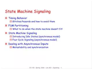
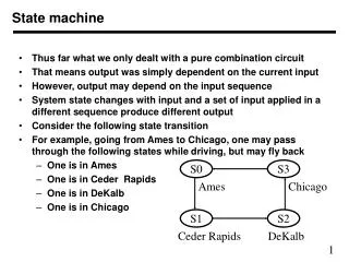
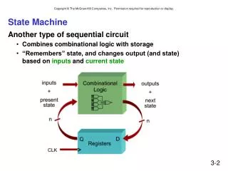
State Machine Definition of State Machine : A synchronous sequential circuit, consisting of a sequential logic section and a combinational logic section, whose outputs and internal flip-flops progress through a predictable sequence of states in response to a clock and other input signals. Like this:
Examples of State Machine There are numerous examples of everyday devices that are controlled by a state machine: Traffic Light Garage Door Numeric Keypad Vending Machine
State Machine Block Diagram ... ... ... ... Input Combo Logic Memory Flip-Flops Output Combo Logic Output(s) Input(s) Clock
State Machine Design Steps • Create State Graph • Determine State Variables & Assign • Encode Outputs to States • Create State Transition Table • Write & Simplify Design Equations • Design Circuit
How to make a state graph Make a bubble for each state. Say you want to display the numbers 415 over and over again in that order. There are 3 states: State 0 = 4 State 1 = 1 State 2 = 5
State Machine Design Example Example: Design a state machine that will count out the three digits 4 1 5 Whenever the Enable is a logic (1), the outputs will continuously cycle through the three values 4,1, 5. Whenever the Enable is a logic (0), the outputs will hold at their current values. “4” “1” “5” C3 C2 C1 C0 Numbers Enable Clock
Anatomy of a State Graph Input Variable ( EN) (Enable switch) When it’s 0 stay in the same state EN = 0 S0 Qa Qb 0 0 A=1 B=0 C=0 State “Bubble” EN = 1 Transition Arc This is where to go when EN=1 State Variables (i.e. Qa & Qb) Says this is state 00 Output Variables What is displayed At state 0 a 4 (100) is displayed
Step #1 : Create State Graph for “415” EN = 0 S0 EN = 1 “4” S1 EN = 1 EN = 0 “1” S2 “5” EN = 1 EN = 0
Step #2 & 3 : Assign variables, Encode Outputs to States EN = 0 S0 EN = 1 EN = 1 Qa Qb 0 0 “4” C2=1 C1=0 C0=0 S1 EN = 0 Qa Qb 0 1 “1” C2=1 C1=0 C0=1 C2=0 C1=0 C0=1 S2 Qa Qb 1 0 “5” EN = 1 EN = 0
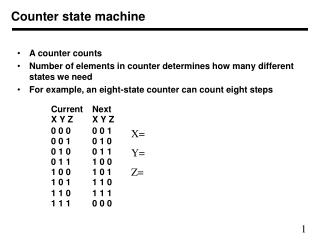
Step #3 : Create State Transition Table Assuming that you are using D flip flops, Da is the input to flip flop A, Db to B
Write and simplify equations The flip flops need to receive the signal so that on the next clock pulse they will change to the next state The next state is determined by the current state and the input. In this case if the Enable is true, it moves to the next state or else if stays at the current output. Da = Qb EN + Qa Db = Qa’ Qb’ EN + Qb EN’ C2 = Qb C1 = 0 (always off) C0 = Qa + Qb
Step #5 : Circuit Design Da = Qb EN + Qa These are the inputs to the flip flops Db = Qa’ Qb’ EN + Qb EN’ Flip flop b Flip flop a ENABLE This is a SPST switch clock C2 = Qb These are the output signals C1 = 0 (always off) C0 = Qa + Qb