Download
1 / 23
230 likes | 380 Views
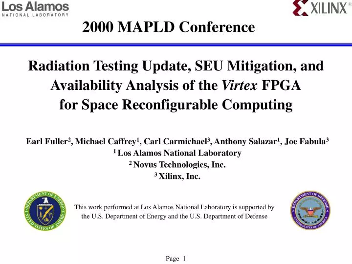
2000 MAPLD Conference. Radiation Testing Update, SEU Mitigation, and Availability Analysis of the Virtex FPGA for Space Reconfigurable Computing. Earl Fuller 2 , Michael Caffrey 1 , Carl Carmichael 3 , Anthony Salazar 1 , Joe Fabula 3 1 Los Alamos National Laboratory

E N D
2000 MAPLD Conference Radiation Testing Update, SEU Mitigation, and Availability Analysis of the Virtex FPGAfor Space Reconfigurable Computing Earl Fuller2, Michael Caffrey1, Carl Carmichael3, Anthony Salazar1, Joe Fabula3 1 Los Alamos National Laboratory 2 Novus Technologies, Inc. 3 Xilinx, Inc. This work performed at Los Alamos National Laboratory is supported by the U.S. Department of Energy and the U.S. Department of Defense Page 1
Abstract • Device Tested: XCV300 SRAM Based FPGA • Radiation Characterization: TID, SEL, Heavy Ion SEU, Proton SEU • Intended Application: Orbital remote sensing instruments • Expected Benefits: Higher system performance, Lower cost Adaptable computing systems • Risks SEUs and their consequences • Mitigation: Techniques tested, benefits measured • Assumption: Occasional loss of data is a tolerable trade for increased processing capability This technology is driven by the commercial sector, so devices intended for the space environment must be adapted from commercial product. Page 2
Virtex FPGA Technology • SRAM-based, Reconfigurable FPGA • 50k to 1M System Gates • 0.22μ CMOS process, epitaxial silicon, 5 metal layers • Tested the XQVR300 Page 3
Radiation Characterization Test Strategy • TID • High dose and low dose exposure • In-situ leakage monitors and full functional and parametric test • Static SEU • Configure and readback all bits via serial scan • Measure upset sensitivity of bit types • Monitor current • Dynamic SEU • Create different designs to highlight blocks of technology • Vary frequency of operation from 5MHz to 80MHz • Measure fluence to dynamic upset • Readback configuration serially to monitor upset bits • Proton Sensitivity • Measure sensitivity for improved upset rate predictions Page 4
TID Test Results High Dose Rate Low Dose Rate • Leakage current monitors show 80k to 100krad(Si) tolerance • Results are validated by full functional and parametric test Page 5
SEL Test Results • Texas A&M Cyclotron, 2068 MeV Au ions • Tested to fluence of 108 ions/cm2 • No latch-up to an LET of 125 MeV-cm2/mg Page 6
Virtex FPGA Static Heavy Ion SEU Sensitivity • An upset in configuration control logic register was observed • Observed threshold LET between 8 and 16 MeV-cm2/mg • Small device cross-section measured at 1 E-5 cm2 for this mode • Small probability of occurrence based on measured cross-section Page 7
Virtex FPGA Static Proton SEU Sensitivity • Configuration control logic register upset noted at 63MeV Page 8
Dynamic Test Strategy • Create different designs to highlight blocks of technology • Configure design for self-test • Vary frequency of operation from 5MHz to 50MHz • Measure fluence to dynamic upset • Readback configuration serially to monitor upset bits • Detection and recovery of static bit upsets • Configuration readback feature allows for continuous monitoring for static bit upsets • Detection and repair is rapid • Partial reconfiguration capability (PRC) allows for recovery without interruption of function • Mitigation requires redundancy techniques Page 9
FIR Design for Dynamic SEU Test • No TMR version is 1/3 the size of the TMR version • Allowance made for bitstream read back & real time reconfigure of SEUs Page 10
“Combo” Test Circuits for Maximum Utilization Device Utilization: Device Utilization: Slices 24% Slices 95% BRAM 100% BRAM 0% • Combo circuit combines both of these designs together Page 11
Bitstream Upsets from Dynamic Tests • Not Every Bit-upset has the same consequence • Bitstream detects 45% of dynamic failures when redundancy is not used • 6.5 bit-upsets average, large standard deviation • Reliable operation requires combination of redundancy and bitstream repair Page 12
Several follow-on Proton Beam Tests • Objectives • Refinement and validation of SEU Mitigation Strategy • Identification of design constraints • Issues addressed • SEU detection & correction via readback & partial reconfiguration • Scrubbing of FPGA configuration • Internal TMR (triple module redundancy) • Floor planning to force a desired location • Vary internal clocking source • Isolate BRAM • Isolate DLL (delay lock loop) • Suppressing unused nodes Page 13
Results of Frequency Tests Varying frequency had no measurable effect on SEU rate Page 14
Results of SEU Mitigation Tests • Combining TMR with PRC results in 15x improvement • Standard deviation of data is large for all data Page 15
CREME96 Orbital Upset Rates Worst-case calculated rates Significant proton sensitivity Page 16
CREME96 Orbital Upset Rates Upset rate estimates with No mitigation: Calculated worst-case, by including all bits Measured dynamic upsets without design mitigation: with No bitstream cause with bitstream cause IEEE 1156.4-1997 Standard Upset rates Using mitigation techniques: Benefit of TMR & PRC Newest data including TMR, scrub, and suppressing unused nodes Improvement of 1100x compared to worst-case Page 17
Time to Upset Time to Restore Time Time Between Upsets Time to First Upset Availability Example Operational Readiness – Availability A = Availability = Mean Time to Upset / Mean Time Between Upsets λ = Upset Frequency = 1 / Mean Time Between Upsets MDT = Mean Down Time = Mean Time to Restore MUT = Mean Up Time = Mean Time to Upset A = MUT / (MUT + MDT) Page 18
Availability Issues • Requirement needs to be defined • Recovery time much more effect on availability that upset rate • Consequence of downtime determined by system engineering • Inherently, Availability can be < 100% • Fault detection is absolutely required to prevent fault propagation • Automation is required to minimize recovery time • Virtex FPGA reconfigures fast (< 50 msec / XQVR1000) Page 19
Worst-case SEU Rates • The upset rates were based on worst-case upset sensitivity analysis of the Virtex parts. • Treating each static bit in the device as if any bit upset causes a functional SEU. • Overstates the error rate. Significant improvement obtained by mitigation methods Page 20
FPGA Recovery Time • The keys are real-time, non-interfering configuration readback and correction, and maximum clock rate • The FPGA bitstream configuration clock rate is 66MHz, (which is faster than the 25MHz PROM) • Virtex SelectMAP interface allows non-interfering readback & configuration • The XCV1000 reconfiguration time is 31msec (768 kbytes / 25MHz) • The full recovery time is system design dependent, latencies will exist in system • An example will use 200msec for availability calculations Page 21
Availability Example Page 22
Availability Conclusion • Rapid recovery enables availability in excess of 99.99% • Occasional loss of data can be a tolerable trade for increased processing capability • SEU rate does not preclude the use of commercial SRAM-based FPGAs Page 23