Download
1 / 12
120 likes | 225 Views
Experimental and Numerical Study of Mist Cooling for the Electra Hibachi V.Novak, D.Sadowski, S.Shin, K.Schoonover, and S. Abdel-Khalik. HAPL meeting, Madison, WI (September, 24-25, 2003). G. W. Woodruff School of Mechanical Engineering Atlanta, GA 30332 – 0405 USA. Diode (vacuum).

E N D
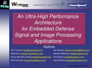
Experimental and Numerical Study of Mist Cooling for the Electra HibachiV.Novak, D.Sadowski, S.Shin, K.Schoonover, and S. Abdel-Khalik HAPL meeting, Madison, WI (September, 24-25, 2003) G. W. Woodruff School of Mechanical Engineering Atlanta, GA 30332–0405 USA
Diode (vacuum) Laser Gas 1.3-2.0 atm (Kr+F2) flow at 4 m/s E-beam Hibachi Foils Hibachi Ribs He(or Air)/ Water mix Water Layers Pressure Foil Anode Foil LASER GAS VACUUM EMITTER E-beam Objectives • Experimentally examine effectiveness of gas/liquid mist as a means of cooling the Electra Hibachi Foils • Quantify effect of various operating parameters on mist cooling effectiveness for prototypical Hibachi geometry (gas/liquid combination, gas velocity, liquid mass fraction, droplet size) • Develop a validated mechanistic model to predict Hibachi foils’ thermal response under prototypical pulsed operating conditions
Experimental ResultsAir/Water Mist Cooling – Rectangluar Channel (24 cm) Air-Assisted Nozzle Average heat transfer coefficient [W/m2K] Average enhancement ratio [h/hdry air] 15m/s 15m/s Ultrasonic Nozzle 10m/s Average heat transfer coefficient [W/m2K] 10m/s 5m/s 5m/s 15m/s Water inlet mass fraction [%] Water inlet mass fraction [%] 10m/s Local heat transfer coefficient [W/m2K] Average heat transfer coefficient [W/m2K] 5m/s 15m/s,15% 15m/s,10% water inlet mass fraction [%] 15m/s,5% Optimization of atomizing air mass fraction (10m/s air,10% water) Max Twall=80-90oC 15m/s,dry air Air-assisted nozzle inlet pressure [psi] Axial distance [cm]
Air/Water Mist Flow [100% Saturation] (Tin=20 oC, 1 atm, rp=30 m) Coolant Distribution Particle Distribution foils (Hastelloy-X =0.25 mm) Coolant Temperature Front Surface Temperature Back Surface Temperature Particle Temperature 2 cm 6 cm Heating (Qw) 60 cm Heating (Qw) insulated side wall 4 cm Numerical Simulation steady state experiment (Air/Water)
Coolant Exit Temperature 0 % water 4 % water 5 % water 10 % water 15 % water dry air (15m/s, Qw=250W) Numerical Simulation steady state experiment (Air/Water) Coolant Bulk Temperature Wall and Coolant Temperature Distribution Pressure P [kPa] T [K] Solid line : Coolant bulk temperature Dash dot line : Wall temperature z [cm] z [cm] Heat transfer coefficient at the wall 15m/s Air Qw=250W rp=30 m Wall film thickness
Coolant Exit Temperature Wall and Coolant Temperature Distribution Solid line : Coolant bulk temperature Dash dot line : Wall temperature T [K] 0 % water 16.7 % water 33.5 % water 50.2 % water dry Helium (30m/s, Qw=250W) Numerical Simulation steady state experiment (Helium/Water) Coolant Bulk Temperature Pressure P [kPa] T [K] z [cm] z [cm] Heat transfer coefficient at the wall 30m/s Helium Qw=250W rp=30 m
Coolant Distribution Particle Distribution Air/Water Mist Flow [0% Saturation] (15m/s Air, 10% Water Tin=20 oC, 1 atm, rp=30m) foils (Titanium, =0.025mm) Coolant Temperature Front Surface Temperature Back Surface Temperature 2 cm Particle Temperature Heating 30 cm Heating Q [W/cm3] 0.1ms insulated side wall 587250 W/cm3 0.1 s time [sec] 0 pulse start at 4.0 s 4 cm Numerical Simulation pulsed heating (10Hz)
Numerical Simulation pulsed heating (10Hz) Coolant Exit Temperature Maximum Temperature at the wall Dry Air Dry Air Air/Water (15m/s, 15%) Air/Water (15m/s, 15%)
A B C t [sec] Numerical Simulation pulsed heating (10Hz) Coolant Temperature Distribution Surface Temperature Distribution Heat Transfer Coefficient Distribution Dry Air Air/Water A : just before pulse B : just after pulse C : one pulse later (15m/s,15%)
Conclusions • Mist cooling provides the means to effectively cool the Electra Hibachi within specified constraints on cooling system power consumption, foil max temperature, and temperature gradient • Heat transfer coefficient can be significantly increased especially for prototypical transient condition • A validated mechanistic model to predict the foils’ thermal response under prototypical conditions has been developed
Future Efforts • Examine effect of liquid film formation on e-beam transmission efficiency • Examine system performance for other gas/liquid combinations • Construct and test a multi-channel test module under prototypical conditions