Download
1 / 1
40 likes | 215 Views
Beam Profiling Using a Scanning Knife Edge Technique James White white@juniata.edu Anthony Baldridge and Brandon Dearman Juniata College August 4, 2003. Overview of Scanning Knife Edge Technique One of the better methods for profiling using mechanical parts

E N D
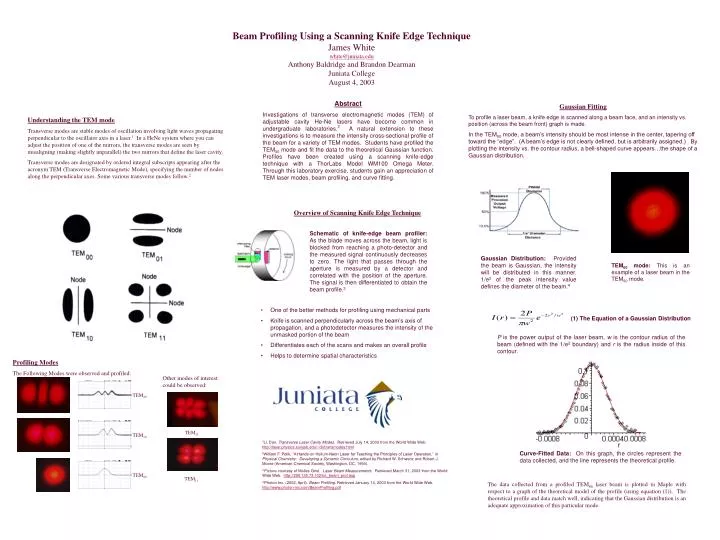
Beam Profiling Using a Scanning Knife Edge TechniqueJames Whitewhite@juniata.eduAnthony Baldridge and Brandon DearmanJuniata CollegeAugust 4, 2003 Overview of Scanning Knife Edge Technique • One of the better methods for profiling using mechanical parts • Knife is scanned perpendicularly across the beam’s axis of propagation, and a photodetector measures the intensity of the unmasked portion of the beam • Differentiates each of the scans and makes an overall profile • Helps to determine spatial characteristics Gaussian Fitting To profile a laser beam, a knife edge is scanned along a beam face, and an intensity vs. position (across the beam front) graph is made. In the TEM00 mode, a beam’s intensity should be most intense in the center, tapering off toward the “edge”. (A beam’s edge is not clearly defined, but is arbitrarily assigned.) By plotting the intensity vs. the contour radius, a bell-shaped curve appears…the shape of a Gaussian distribution. Abstract Investigations of transverse electromagnetic modes (TEM) of adjustable cavity He-Ne lasers have become common in undergraduate laboratories.2 A natural extension to these investigations is to measure the intensity cross-sectional profile of the beam for a variety of TEM modes. Students have profiled the TEM00 mode and fit the data to the theoretical Gaussian function. Profiles have been created using a scanning knife-edge technique with a ThorLabs Model WM100 Omega Meter. Through this laboratory exercise, students gain an appreciation of TEM laser modes, beam profiling, and curve fitting. Understanding the TEM mode Transverse modes are stable modes of oscillation involving light waves propagating perpendicular to the oscillator axis in a laser.1 In a HeNe system where you can adjust the position of one of the mirrors, the transverse modes are seen by misaligning (making slightly unparallel) the two mirrors that define the laser cavity. Transverse modes are designated by ordered integral subscripts appearing after the acronym TEM (Transverse Electromagnetic Mode), specifying the number of nodes along the perpendicular axes. Some various transverse modes follow.2 Schematic of knife-edge beam profiler: As the blade moves across the beam, light is blocked from reaching a photo-detector and the measured signal continuously decreases to zero. The light that passes through the aperture is measured by a detector and correlated with the position of the aperture. The signal is then differentiated to obtain the beam profile.3 Gaussian Distribution: Provided the beam is Gaussian, the intensity will be distributed in this manner. 1/e2 of the peak intensity value defines the diameter of the beam.4 TEM00 mode: This is an example of a laser beam in the TEM00 mode. (1) The Equation of a Gaussian Distribution P is the power output of the laser beam, w is the contour radius of the beam (defined with the 1/e2 boundary) and r is the radius inside of this contour. Profiling Modes The Following Modes were observed and profiled: Other modes of interest could be observed: TEM20 TEM21 TEM10 1Li, Dan, Transverse Laser Cavity Modes. Retrieved July 14, 2003 from the World Wide Web. http://laser.physics.sunysb.edu/~dli/transmodes.html 2William F. Polik, “A Hands-on Helium-Neon Laser for Teaching the Principles of Laser Operation,” in Physical Chemistry: Developing a Dynamic Cirriculum, edited by Richard W. Schwenz and Robert J. Moore (American Chemical Society, Washington, DC, 1993). 3 Picture courtesy of Melles Griot. Laser Beam Measurements. Retrieved March 31, 2003 from the World Wide Web. http://206.135.73.102/tut_beam_prof.asp 4 Photon Inc. (2002, April). Beam Profiling. Retrieved January 14, 2003 from the World Wide Web. http://www.photon-inc.com/BeamProfiling.pdf Curve-Fitted Data: On this graph, the circles represent the data collected, and the line represents the theoretical profile. TEM00 TEM11 The data collected from a profiled TEM00 laser beam is plotted in Maple with respect to a graph of the theoretical model of the profile (using equation (1)). The theoretical profile and data match well, indicating that the Gaussian distribution is an adequate approximation of this particular mode.