Download
1 / 124
1.25k likes | 1.44k Views
G9 – Antennas and Feedlines [4 exam questions - 4 groups]. G9A - Antenna feed lines: characteristic impedance and attenuation; SWR calculation, measurement and effects; matching networks G9B - Basic antennas G9C - Directional antennas G9D - Specialized antennas. Feedlines. Standing Waves.

E N D
G9 – Antennas and Feedlines[4 exam questions - 4 groups] • G9A - Antenna feed lines: characteristic impedance and attenuation; SWR calculation, measurement and effects; matching networks • G9B - Basic antennas • G9C - Directional antennas • G9D - Specialized antennas G9 - Antennas
Feedlines G9 - Antennas
Standing Waves G9 - Antennas
G9A01 Which of the following factors determine the characteristic impedance of a parallel conductor antenna feed line? • A. The distance between the centers of the conductors and the radius of the conductors • B. The distance between the centers of the conductors and the length of the line • C. The radius of the conductors and the frequency of the signal • D. The frequency of the signal and the length of the line G9 - Antennas
G9A01 Which of the following factors determine the characteristic impedance of a parallel conductor antenna feed line? • A. The distance between the centers of the conductors and the radius of the conductors • B. The distance between the centers of the conductors and the length of the line • C. The radius of the conductors and the frequency of the signal • D. The frequency of the signal and the length of the line G9 - Antennas
G9A02 What are the typical characteristic impedances of coaxial cables used for antenna feed lines at amateur stations? • A. 25 and 30 ohms • B. 50 and 75 ohms • C. 80 and 100 ohms • D. 500 and 750 ohms G9 - Antennas
G9A02 What are the typical characteristic impedances of coaxial cables used for antenna feed lines at amateur stations? • A. 25 and 30 ohms • B. 50 and 75 ohms • C. 80 and 100 ohms • D. 500 and 750 ohms G9 - Antennas
G9A03 What is the characteristic impedance of flat ribbon TV type twinlead? • A. 50 ohms • B. 75 ohms • C. 100 ohms • D. 300 ohms G9 - Antennas
G9A03 What is the characteristic impedance of flat ribbon TV type twinlead? • A. 50 ohms • B. 75 ohms • C. 100 ohms • D. 300 ohms G9 - Antennas
G9A04 What is the reason for the occurrence of reflected power at the point where a feed line connects to an antenna? • A. Operating an antenna at its resonant frequency • B. Using more transmitter power than the antenna can handle • C. A difference between feed-line impedance and antenna feed-point impedance • D. Feeding the antenna with unbalanced feed line G9 - Antennas
G9A04 What is the reason for the occurrence of reflected power at the point where a feed line connects to an antenna? • A. Operating an antenna at its resonant frequency • B. Using more transmitter power than the antenna can handle • C. A difference between feed-line impedance and antenna feed-point impedance • D. Feeding the antenna with unbalanced feed line G9 - Antennas
G9A05 How does the attenuation of coaxial cable change as the frequency of the signal it is carrying increases? • A. It is independent of frequency • B. It increases • C. It decreases • D. It reaches a maximum at approximately 18 MHz G9 - Antennas
G9A05 How does the attenuation of coaxial cable change as the frequency of the signal it is carrying increases? • A. It is independent of frequency • B. It increases • C. It decreases • D. It reaches a maximum at approximately 18 MHz G9 - Antennas
G9A06 In what values are RF feed line losses usually expressed? • A. ohms per 1000 ft • B. dB per 1000 ft • C. ohms per 100 ft • D. dB per 100 ft G9 - Antennas
G9A06 In what values are RF feed line losses usually expressed? • A. ohms per 1000 ft • B. dB per 1000 ft • C. ohms per 100 ft • D. dB per 100 ft G9 - Antennas
G9A07 What must be done to prevent standing waves on an antenna feed line? • A. The antenna feed point must be at DC ground potential • B. The feed line must be cut to an odd number of electrical quarter wavelengths long • C. The feed line must be cut to an even number of physical half wavelengths long • D. The antenna feed-point impedance must be matched to the characteristic impedance of the feed line G9 - Antennas
G9A07 What must be done to prevent standing waves on an antenna feed line? • A. The antenna feed point must be at DC ground potential • B. The feed line must be cut to an odd number of electrical quarter wavelengths long • C. The feed line must be cut to an even number of physical half wavelengths long • D. The antenna feed-point impedance must be matched to the characteristic impedance of the feed line G9 - Antennas
G9A08 If the SWR on an antenna feed line is 5 to 1, and a matching network at the transmitter end of the feed line is adjusted to 1 to 1 SWR, what is the resulting SWR on the feed line? • A. 1 to 1 • B. 5 to 1 • C. Between 1 to 1 and 5 to 1 depending on the characteristic impedance of the line • D. Between 1 to 1 and 5 to 1 depending on the reflected power at the transmitter G9 - Antennas
G9A08 If the SWR on an antenna feed line is 5 to 1, and a matching network at the transmitter end of the feed line is adjusted to 1 to 1 SWR, what is the resulting SWR on the feed line? • A. 1 to 1 • B. 5 to 1 • C. Between 1 to 1 and 5 to 1 depending on the characteristic impedance of the line • D. Between 1 to 1 and 5 to 1 depending on the reflected power at the transmitter G9 - Antennas
G9A09 What standing wave ratio will result from the connection of a 50-ohm feed line to a non-reactive load having a 200-ohm impedance? • A. 4:1 • B. 1:4 • C. 2:1 • D. 1:2 G9 - Antennas
G9A09 What standing wave ratio will result from the connection of a 50-ohm feed line to a non-reactive load having a 200-ohm impedance? • A. 4:1 • B. 1:4 • C. 2:1 • D. 1:2 G9 - Antennas
G9A10 What standing wave ratio will result from the connection of a 50-ohm feed line to a non-reactive load having a 10-ohm impedance? • A. 2:1 • B. 50:1 • C. 1:5 • D. 5:1 G9 - Antennas
G9A10 What standing wave ratio will result from the connection of a 50-ohm feed line to a non-reactive load having a 10-ohm impedance? • A. 2:1 • B. 50:1 • C. 1:5 • D. 5:1 G9 - Antennas
G9A11 What standing wave ratio will result from the connection of a 50-ohm feed line to a non-reactive load having a 50-ohm impedance? • A. 2:1 • B. 1:1 • C. 50:50 • D. 0:0 G9 - Antennas
G9A11 What standing wave ratio will result from the connection of a 50-ohm feed line to a non-reactive load having a 50-ohm impedance? • A. 2:1 • B. 1:1 • C. 50:50 • D. 0:0 G9 - Antennas
G9A12 What would be the SWR if you feed a vertical antenna that has a 25-ohm feed-point impedance with 50-ohm coaxial cable? • A. 2:1 • B. 2.5:1 • C. 1.25:1 • D. You cannot determine SWR from impedance values G9 - Antennas
G9A12 What would be the SWR if you feed a vertical antenna that has a 25-ohm feed-point impedance with 50-ohm coaxial cable? • A. 2:1 • B. 2.5:1 • C. 1.25:1 • D. You cannot determine SWR from impedance values G9 - Antennas
G9A13 What would be the SWR if you feed an antenna that has a 300-ohm feed-point impedance with 50-ohm coaxial cable? • A. 1.5:1 • B. 3:1 • C. 6:1 • D. You cannot determine SWR from impedance values G9 - Antennas
G9A13 What would be the SWR if you feed an antenna that has a 300-ohm feed-point impedance with 50-ohm coaxial cable? • A. 1.5:1 • B. 3:1 • C. 6:1 • D. You cannot determine SWR from impedance values G9 - Antennas
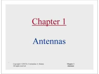
Vertical Antennas(Quarter Wavelength Vertical) Radials Ground Plane Ground Marconi Ground Plane Quarter wavelength 300 F (MHz) Wavelength (meters) = Meters to inches ¼λ vertical length (inches) = Wavelength / 4 x 39 G9 - Antennas
Vertical Antenna • Standard ¼ wave vertical has a feedpoint impedance of ~35 ohms • Sloping ground radials downward raises feedpoint impedance G9 - Antennas
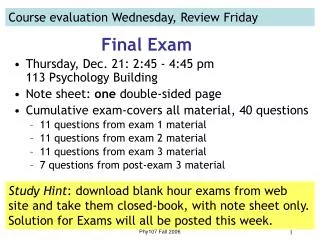
½ λ Dipole Radiation Radiation pattern for a dipole placed ½ λ above ground looking down from above the antenna. Looks like a doughnut around the wire in 3D space. Pattern distorts to omnidirectional when placed low to the ground. G9 - Antennas
G9B01 What is one disadvantage of a directly fed random-wire antenna? • A. It must be longer than 1 wavelength • B. You may experience RF burns when touching metal objects in your station • C. It produces only vertically polarized radiation • D. It is not effective on the higher HF bands G9 - Antennas
G9B01 What is one disadvantage of a directly fed random-wire antenna? • A. It must be longer than 1 wavelength • B. You may experience RF burns when touching metal objects in your station • C. It produces only vertically polarized radiation • D. It is not effective on the higher HF bands G9 - Antennas
G9B02 What is an advantage of downward sloping radials on a quarter wave ground-plane antenna? • A. They lower the radiation angle • B. They bring the feed-point impedance closer to 300 ohms • C. They increase the radiation angle • D. They bring the feed-point impedance closer to 50 ohms G9 - Antennas
G9B02 What is an advantage of downward sloping radials on a quarter wave ground-plane antenna? • A. They lower the radiation angle • B. They bring the feed-point impedance closer to 300 ohms • C. They increase the radiation angle • D. They bring the feed-point impedance closer to 50 ohms G9 - Antennas
G9B03 What happens to the feed-point impedance of a ground-plane antenna when its radials are changed from horizontal to downward-sloping? • A. It decreases • B. It increases • C. It stays the same • D. It reaches a maximum at an angle of 45 degrees G9 - Antennas
G9B03 What happens to the feed-point impedance of a ground-plane antenna when its radials are changed from horizontal to downward-sloping? • A. It decreases • B. It increases • C. It stays the same • D. It reaches a maximum at an angle of 45 degrees G9 - Antennas
G9B04 What is the low angle azimuthal radiation pattern of an ideal half-wavelength dipole antenna installed 1/2 wavelength high and parallel to the Earth? • A. It is a figure-eight at right angles to the antenna • B. It is a figure-eight off both ends of the antenna • C. It is a circle (equal radiation in all directions) • D. It has a pair of lobes on one side of the antenna and a single lobe on the other side G9 - Antennas
G9B04 What is the low angle azimuthal radiation pattern of an ideal half-wavelength dipole antenna installed 1/2 wavelength high and parallel to the Earth? • A. It is a figure-eight at right angles to the antenna • B. It is a figure-eight off both ends of the antenna • C. It is a circle (equal radiation in all directions) • D. It has a pair of lobes on one side of the antenna and a single lobe on the other side G9 - Antennas
G9B05 How does antenna height affect the horizontal (azimuthal) radiation pattern of a horizontal dipole HF antenna? • A. If the antenna is too high, the pattern becomes unpredictable • B. Antenna height has no effect on the pattern • C. If the antenna is less than 1/2 wavelength high, the azimuthal pattern is almost omnidirectional • D. If the antenna is less than 1/2 wavelength high, radiation off the ends of the wire is eliminated G9 - Antennas
G9B05 How does antenna height affect the horizontal (azimuthal) radiation pattern of a horizontal dipole HF antenna? • A. If the antenna is too high, the pattern becomes unpredictable • B. Antenna height has no effect on the pattern • C. If the antenna is less than 1/2 wavelength high, the azimuthal pattern is almost omnidirectional • D. If the antenna is less than 1/2 wavelength high, radiation off the ends of the wire is eliminated G9 - Antennas
G9B06 Where should the radial wires of a ground-mounted vertical antenna system be placed? • A. As high as possible above the ground • B. Parallel to the antenna element • C. On the surface or buried a few inches below the ground • D. At the top of the antenna G9 - Antennas
G9B06 Where should the radial wires of a ground-mounted vertical antenna system be placed? • A. As high as possible above the ground • B. Parallel to the antenna element • C. On the surface or buried a few inches below the ground • D. At the top of the antenna G9 - Antennas
G9B07 How does the feed-point impedance of a 1/2 wave dipole antenna change as the antenna is lowered from 1/4 wave above ground? • A. It steadily increases • B. It steadily decreases • C. It peaks at about 1/8 wavelength above ground • D. It is unaffected by the height above ground G9 - Antennas
G9B07 How does the feed-point impedance of a 1/2 wave dipole antenna change as the antenna is lowered from 1/4 wave above ground? • A. It steadily increases • B. It steadily decreases • C. It peaks at about 1/8 wavelength above ground • D. It is unaffected by the height above ground G9 - Antennas
G9B08 How does the feed-point impedance of a 1/2 wave dipole change as the feed-point location is moved from the center toward the ends? • A. It steadily increases • B. It steadily decreases • C. It peaks at about 1/8 wavelength from the end • D. It is unaffected by the location of the feed point G9 - Antennas
G9B08 How does the feed-point impedance of a 1/2 wave dipole change as the feed-point location is moved from the center toward the ends? • A. It steadily increases • B. It steadily decreases • C. It peaks at about 1/8 wavelength from the end • D. It is unaffected by the location of the feed point G9 - Antennas
G9B09 Which of the following is an advantage of a horizontally polarized as compared to vertically polarized HF antenna? • A. Lower ground reflection losses • B. Lower feed-point impedance • C. Shorter Radials • D. Lower radiation resistance G9 - Antennas

![G5 - ELECTRICAL PRINCIPLES [3 exam questions - 3 groups]](https://cdn0.slideserve.com/589616/g5-electrical-principles-3-exam-questions-3-groups-dt.jpg)
![G2 - OPERATING PROCEDURES [5 Exam Questions -- 5 Groups]](https://cdn0.slideserve.com/813501/g2-operating-procedures-5-exam-questions-5-groups-dt.jpg)
![G3 - RADIO WAVE PROPAGATION [3 Exam Questions -- 3 Groups]](https://cdn0.slideserve.com/819386/g3-radio-wave-propagation-3-exam-questions-3-groups-dt.jpg)
![G8 - SIGNALS AND EMISSIONS [2 exam questions - 2 groups]](https://cdn0.slideserve.com/1199451/g8-signals-and-emissions-2-exam-questions-2-groups-dt.jpg)


![G0 - ELECTRICAL AND RF SAFETY [2 Exam Questions - 2 groups]](https://cdn2.slideserve.com/3944556/g0-electrical-and-rf-safety-2-exam-questions-2-groups-dt.jpg)
![G9 - ANTENNAS [4 exam questions - 4 groups]](https://cdn2.slideserve.com/4680506/g9-antennas-4-exam-questions-4-groups-dt.jpg)
![T1 - FCC Rules [4 exam questions – 4 groups]](https://cdn3.slideserve.com/5753656/t1-fcc-rules-4-exam-questions-4-groups-dt.jpg)