Download
1 / 142
1.44k likes | 1.73k Views
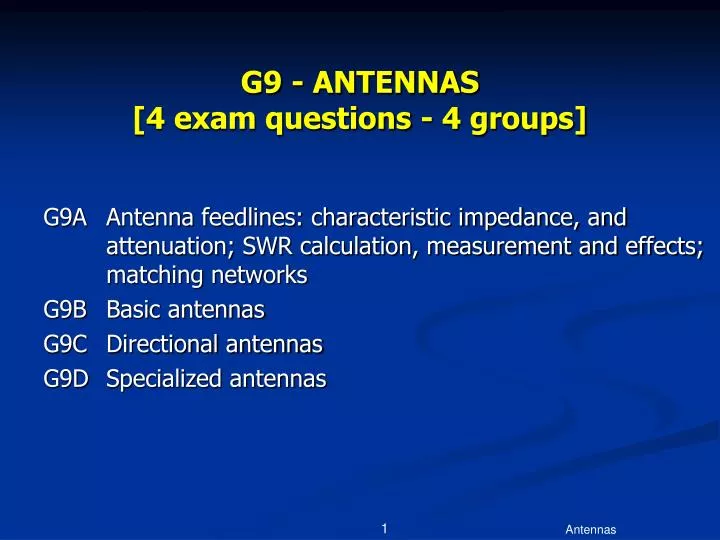
G9 - ANTENNAS [4 exam questions - 4 groups]. G9A Antenna feedlines: characteristic impedance, and attenuation; SWR calculation, measurement and effects; matching networks G9B Basic antennas G9C Directional antennas G9D Specialized antennas. Feedlines.

E N D
G9 - ANTENNAS [4 exam questions - 4 groups] • G9A Antenna feedlines: characteristic impedance, and attenuation; SWR calculation, measurement and effects; matching networks • G9B Basic antennas • G9C Directional antennas • G9D Specialized antennas Antennas
Feedlines Antennas
G9A01 Which of the following factors help determine the characteristic impedance of a parallel conductor antenna feedline? • A. The distance between the centers of the conductors and the radius of the conductors • B. The distance between the centers of the conductors and the length of the line • C. The radius of the conductors and the frequency of the signal • D. The frequency of the signal and the length of the line Antennas
G9A01 Which of the following factors help determine the characteristic impedance of a parallel conductor antenna feedline? • A. The distance between the centers of the conductors and the radius of the conductors Antennas
G9A02 What is the typical characteristic impedance of coaxial cables used for antenna feedlines at amateur stations? • A. 25 and 30 ohms • B. 50 and 75 ohms • C. 80 and 100 ohms • D. 500 and 750 ohms Antennas
G9A02 What is the typical characteristic impedance of coaxial cables used for antenna feedlines at amateur stations? • A. 25 and 30 ohms • B. 50 and 75 ohms • C. 80 and 100 ohms • D. 500 and 750 ohms Antennas
G9A03 What is the characteristic impedance of flat ribbon TV type twin lead? • A. 50 ohms • B. 75 ohms • C. 100 ohms • D. 300 ohms Antennas
G9A03 What is the characteristic impedance of flat ribbon TV type twin lead? • A. 50 ohms • B. 75 ohms • C. 100 ohms • D. 300 ohms Antennas
Standing Waves Waves traveling through a transmission line will continue until they meet an obstruction – a change in impedance. Antennas
Standing Waves An open or short will result in the complete reflection of the wave shown on the right. This would create a perfect standing wave. Antennas
Standing Waves In cases where there is simply an impedance mismatch, only some of the energy would be reflected creating smaller standing waves. These standing waves are energy lost, although whatever isn’t lost in the feed line will eventually reflect and radiate. Antennas
G9A04 What is a common reason for the occurrence of reflected power at the point where a feedline connects to an antenna? • A. Operating an antenna at its resonant frequency • B. Using more transmitter power than the antenna can handle • C. A difference between feedline impedance and antenna feed point impedance • D. Feeding the antenna with unbalanced feedline Antennas
G9A04 What is a common reason for the occurrence of reflected power at the point where a feedline connects to an antenna? • A. Operating an antenna at its resonant frequency • B. Using more transmitter power than the antenna can handle • C. A difference between feedline impedance and antenna feed point impedance • D. Feeding the antenna with unbalanced feedline Antennas
G9A05 What must be done to prevent standing waves on an antenna feedline? • A. The antenna feed point must be at DC ground potential • B. The feedline must be cut to an odd number of electrical quarter wavelengths long • C. The feedline must be cut to an even number of physical half wavelengths long • D. The antenna feed point impedance must be matched to the characteristic impedance of the feedline Antennas
G9A05 What must be done to prevent standing waves on an antenna feedline? • D. The antenna feed point impedance must be matched to the characteristic impedance of the feedlineRemember, Match Impedance for maximum transfer of power. Antennas
G9A06 Which of the following is a reason for using an inductively coupled matching network between the transmitter and parallel conductor feed line feeding an antenna? • A. To increase the radiation resistance • B. To reduce spurious emissions • C. To match the unbalanced transmitter output to the balanced parallel conductor feedline • D. To reduce the feed-point impedance of the antenna Antennas
G9A06 Which of the following is a reason for using an inductively coupled matching network between the transmitter and parallel conductor feed line feeding an antenna? • C. To match the unbalanced transmitter output to the balanced parallel conductor feedline Antennas
G9A07 How does the attenuation of coaxial cable change as the frequency of the signal it is carrying increases? • A. It is independent of frequency • B. It increases • C. It decreases • D. It reaches a maximum at approximately 18 MHz Antennas
G9A07 How does the attenuation of coaxial cable change as the frequency of the signal it is carrying increases? • B. It increases Antennas
G9A08 In what values are RF feed line losses usually expressed? • A. ohms per 1000 ft • B. dB per 1000 ft • C. ohms per 100 ft • D. dB per 100 ft Antennas
G9A08 In what values are RF feed line losses usually expressed? • D. dB per 100 ft Antennas
G9A09 What standing-wave-ratio will result from the connection of a 50-ohm feed line to a non-reactive load having a 200-ohm impedance? • A. 4:1 • B. 1:4 • C. 2:1 • D. 1:2 Antennas
G9A09 What standing-wave-ratio will result from the connection of a 50-ohm feed line to a non-reactive load having a 200-ohm impedance? • A. 4:1 • B. 1:4 • C. 2:1 • D. 1:2 Antennas
G9A10 What standing-wave-ratio will result from the connection of a 50-ohm feed line to a non-reactive load having a 10-ohm impedance? • A. 2:1 • B. 50:1 • C. 1:5 • D. 5:1 Antennas
G9A10 What standing-wave-ratio will result from the connection of a 50-ohm feed line to a non-reactive load having a 10-ohm impedance? • A. 2:1 • B. 50:1 • C. 1:5 • D. 5:1 Antennas
G9A11 What standing-wave-ratio will result from the connection of a 50-ohm feed line to a non-reactive load having a 50-ohm impedance? • A. 2:1 • B. 1:1 • C. 50:50 • D. 0:0 Antennas
G9A11 What standing-wave-ratio will result from the connection of a 50-ohm feed line to a non-reactive load having a 50-ohm impedance? • A. 2:1 • B. 1:1 • C. 50:50 • D. 0:0 Antennas
G9A12 What would be the SWR if you feed a vertical antenna that has a 25-ohm feed-point impedance with 50-ohm coaxial cable? • A. 2:1 • B. 2.5:1 • C. 1.25:1 • D. You cannot determine SWR from impedance values Antennas
G9A12 What would be the SWR if you feed a vertical antenna that has a 25-ohm feed-point impedance with 50-ohm coaxial cable? • A. 2:1 • B. 2.5:1 • C. 1.25:1 • D. You cannot determine SWR from impedance values Antennas
G9A13 What would be the SWR if you feed a folded dipole antenna that has a 300-ohm feed-point impedance with 50-ohm coaxial cable? • A. 1.5:1 • B. 3:1 • C. 6:1 • D. You cannot determine SWR from impedance values Antennas
G9A13 What would be the SWR if you feed a folded dipole antenna that has a 300-ohm feed-point impedance with 50-ohm coaxial cable? • A. 1.5:1 • B. 3:1 • C. 6:1 • D. You cannot determine SWR from impedance values Antennas
G9A14 If the SWR on an antenna feedline is 5 to 1, and a matching network at the transmitter end of the feedline is adjusted to 1 to 1 SWR, what is the resulting SWR on the feedline? • A. 1 to 1 • B. 5 to 1 • C. Between 1 to 1 and 5 to 1 depending on the characteristic impedance of the line • D. Between 1 to 1 and 5 to 1 depending on the reflected power at the transmitter Antennas
G9A14 If the SWR on an antenna feedline is 5 to 1, and a matching network at the transmitter end of the feedline is adjusted to 1 to 1 SWR, what is the resulting SWR on the feedline? • B. 5 to 1 Antennas
G9B01 What is one disadvantage of a directly fed random-wire antenna? • A. It must be longer than 1 wavelength • B. You may experience RF burns when touching metal objects in your station • C. It produces only vertically polarized radiation • D. It is not effective on the higher HF bands Antennas
G9B01 What is one disadvantage of a directly fed random-wire antenna? • B. You may experience RF burns when touching metal objects in your station Antennas
Vertical Antennas(Quarter Wavelength Vertical) Radials Ground Plane Ground Marconi Ground Plane Quarter wavelength 300 F (MHz) Wavelength (meters) = Meters to inches ¼λ vertical length (inches) = Wavelength / 4 x 39 Antennas
Vertical Antenna • Standard ¼ wave vertical has a feedpoint impedance of ~35 ohms • Sloping ground radials downward raises feedpoint impedance Antennas
G9B02 What is an advantage of downward sloping radials on a ground-plane antenna? • A. They lower the radiation angle • B. They bring the feed-point impedance closer to 300 ohms • C. They increase the radiation angle • D. They can be adjusted to bring the feed-point impedance closer to 50 ohms Antennas
G9B02 What is an advantage of downward sloping radials on a ground-plane antenna? • A. They lower the radiation angle • B. They bring the feed-point impedance closer to 300 ohms • C. They increase the radiation angle • D. They can be adjusted to bring the feed-point impedance closer to 50 ohms Antennas
G9B03 What happens to the feed-point impedance of a ground-plane antenna when its radials are changed from horizontal to downward-sloping? • A. It decreases • B. It increases • C. It stays the same • D. It reaches a maximum at an angle of 45 degrees Antennas
G9B03 What happens to the feed-point impedance of a ground-plane antenna when its radials are changed from horizontal to downward-sloping? • A. It decreases • B. It increases • C. It stays the same • D. It reaches a maximum at an angle of 45 degrees Antennas
½ λ Dipole Radiation Radiation pattern for a dipole placed ½ λ above ground looking down from above the antenna. Looks like a doughnut around the wire in 3D space. Pattern distorts to omnidirectional when placed low to the ground. Antennas
G9B04 What is the low angle azimuthal radiation pattern of an ideal half-wavelength dipole antenna installed 1/2 wavelength high and parallel to the earth? • A. It is a figure-eight at right angles to the antenna • B. It is a figure-eight off both ends of the antenna • C. It is a circle (equal radiation in all directions) • D. It has a pair of lobes on one side of the antenna and a single lobe on the other side Antennas
G9B04 What is the low angle azimuthal radiation pattern of an ideal half-wavelength dipole antenna installed 1/2 wavelength high and parallel to the earth? • A. It is a figure-eight at right angles to the antenna Antennas
G9B05 How does antenna height affect the horizontal (azimuthal) radiation pattern of a horizontal dipole HF antenna? • A. If the antenna is too high, the pattern becomes unpredictable • B. Antenna height has no effect on the pattern • C. If the antenna is less than 1/2 wavelength high, the azimuthal pattern is almost omnidirectional • D. If the antenna is less than 1/2 wavelength high, radiation off the ends of the wire is eliminated Antennas
G9B05 How does antenna height affect the horizontal (azimuthal) radiation pattern of a horizontal dipole HF antenna? • C. If the antenna is less than 1/2 wavelength high, the azimuthal pattern is almost omnidirectional “Pattern distorts to omnidirectional when placed low to the ground.” Antennas
G9B06 Where should the radial wires of a ground-mounted vertical antenna system be placed? • A. As high as possible above the ground • B. Parallel to the antenna element • C. On the surface or buried a few inches below the ground • D. At the top of the antenna Antennas
G9B06 Where should the radial wires of a ground-mounted vertical antenna system be placed? • A. As high as possible above the ground • B. Parallel to the antenna element • C. On the surface or buried a few inches below the ground • D. At the top of the antenna Antennas
G9B07 How does the feed-point impedance of a 1/2 wave dipole antenna change as the antenna is lowered from 1/4 wave above ground? • A. It steadily increases • B. It steadily decreases • C. It peaks at about 1/8 wavelength above ground • D. It is unaffected by the height above ground Antennas

![SUBELEMENT T3 [3 Exam Questions - 3 Groups]](https://cdn0.slideserve.com/436315/subelement-t3-3-exam-questions-3-groups-dt.jpg)
![SUBELEMENT T3 [3 Exam Questions - 3 Groups]](https://cdn0.slideserve.com/638515/subelement-t3-3-exam-questions-3-groups-dt.jpg)
![SUBELEMENT T0 [3 Exam Questions - 3 Groups]](https://cdn0.slideserve.com/706735/subelement-t0-3-exam-questions-3-groups-dt.jpg)
![SUBELEMENT T4 [2 Exam Questions - 2 Groups]](https://cdn0.slideserve.com/815760/subelement-t4-2-exam-questions-2-groups-dt.jpg)
![G8 - SIGNALS AND EMISSIONS [2 exam questions - 2 groups]](https://cdn1.slideserve.com/2686295/g8-signals-and-emissions-2-exam-questions-2-groups-dt.jpg)

![G8 - SIGNALS AND EMISSIONS [2 exam questions - 2 groups]](https://cdn2.slideserve.com/4523720/g8-signals-and-emissions-2-exam-questions-2-groups-dt.jpg)
![G1 - COMMISSION'S RULES [5 Exam Questions -- 5 Groups]](https://cdn3.slideserve.com/6477195/g1-commission-s-rules-5-exam-questions-5-groups-dt.jpg)