Download
1 / 59
620 likes | 781 Views
Multi-Layer Phase-Change Electronic Memory Devices. Kris Campbell Associate Professor Dept. of Electrical and Computer Engineering & Dept. of Materials Science and Engineering Boise State University. Introduction. Chalcogenide-based memories – why do we need a new memory technology?

E N D
Multi-Layer Phase-Change Electronic Memory Devices Kris Campbell Associate Professor Dept. of Electrical and Computer Engineering & Dept. of Materials Science and Engineering Boise State University University of Idaho ECE Research Colloquium March 8, 2007
Introduction • Chalcogenide-based memories – why do we need a new memory technology? • Types of chalcogenide resistive memories – ion conducting and phase-change • Chalcogenide memory stack structures • Tuning the phase-change memory operating parameters • With materials • Electrically • Summary
What is a Chalcogenide Material? A Chalcogenide material contains one of the Group VI elements S, Se, or Te (O is usually omitted). Some examples of chalcogenides: • GeS – germanium sulfide • SnSe – tin selenide • ZnTe – zinc telluride
Uses of Chalcogenide Materials Memory (CD’s, electronic) Energy generation (solar cells) Chalcogenide materials are key to many new technology developments Photodetectors Environmental pollutant detection Energy storage (batteries)
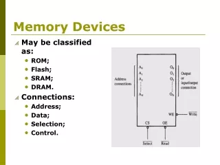
Why Are New Memory Technologies Under Development? • Could replace both DRAM and Flash memory types • DRAM has reached a size scaling limitation and is volatile • Flash is prone to radiation damage, is high power, and has a short cycling lifetime • Radiation resistant • Scalable • Low power operation • Reconfigurable electronics applications • Potential for multiple resistance states (means multiple data states in a single bit)
Chalcogenide materials can be used as resistance variable memory cells: Logic ‘0’ state: Rcell> 200 kΩ Logic ‘1’ state: Rcell= 200 Ω to 100 kΩ The resistance ranges vary quite a bit depending upon the material used. V V Write, Vw 10 kΩ 1 MΩ Erase, Ve ‘1’ ‘0’ OFF ON How Does a Chalcogenide Material Act as a Memory?
ON and OFF State Distributions • Resistance values in the ON and OFF states have a distribution of values; • Threshold voltages or programming currents for ON and OFF states also have a distribution of possible values.
Single Bit Test Structure Device is here Top down view
Types of Chalcogenide Resistive Memory • Ion-Conducting • Ions (e.g. Ag+ and Cu+) are added to a chalcogenide glass • Application of electric field causes formation of a conductive channel through glass(Kozicki, M.N. et al., Microelectronic Engineering63,485 (2002)) • Thermally Induced Phase Change • Crystalline to amorphous phase change; low R tohigh R shift • High current heats material to cause phase change(S.R. Ovshinsky, Phys. Rev. Lett.21, 1450 (1968))
(Ge40Se60)33 (Ag2Se)67 Ion-Conducting Memories • Resistance variable memory based on Ag+ mobility in a chalcogenide glass; • Ag is photodoped into a GexSe100-x based chalcogenide glass (x<33). Visible light Ag Ge30Se70 Developed by Axon Technologies (http://www.axontc.com)
Ion-Conducting Memories - Operation • A positive potential applied to the Ag electrode writes the bit to a low resistance state; • A negative potential applied to the Ag-containing electrode erases the bit to a high resistance state. - +
Ag V (Ge30Se70)67Ag33 W Ion-Conducting Chalcogenide-Based Memories Example material: Ge30Se70 photodoped with Ag From Kozicki, et al. NVMTS, Nov. 2004.
Glasses in region I phase separate and form Ag2Se. Glasses in region II will not phase separate Ag2Se but will put Ag on the glass backbone. Photodoped Ge30Se70 will form 32% Ge40Se60 and 68% Ag2Se. Why is Glass Stoichiometry Important For Photodoping? Mitkova, M.; et al.,Phys. Rev. Lett.83 (1999) 3848-3851.
Traditional Ion-Conducting Structure vs Stack Structure Top electrode Ag Ag2+xSe Ge30Se70 Ge40Se60 Bottom electrode Bottom electrode Traditional Ion-Conducting Memory Structure Stacked Layer Ion-Conducting Memory Structure
‘1’ Low R ‘0’ High R Vw Ve Ag2Se-Based Ion-Conducting Memory(Instead of Photodoping with Ag)
Ion-Conducting Memory Improvement • Ag2Se can be replaced with other metal-chalcogenides. • Examples: SnSe, PbSe, SnTe, Sb2Se3 • The Ge-chalcogenide must contain Ge-Ge bonds. • GeSe-based materials are more stable than S or Te containing materials.
‘1’ Low R ‘0’ High R Vw Ve Ion-Conducting Memory Improvement • Eliminate Ag photodoping • Use a metal-chalcogenide layer above a GexSe100-x glass with carefully selected stoichiometry Metal Chalcogenide
Ion-Conducting Memory Research Projects • Investigate operational mechanism: • Influence of metal in the Metal-Se layer. Role of redox potential • Glass – rigid or floppy • Type of mobile ion (e.g. Ag or Cu) • Effects of these on memory properties: • switching speed • power • data retention • resistance distribution • thermal tolerance
What Are Phase-Change Materials? • Materials that change their electrical resistance when they are switched between crystalline and glassy (disordered) structures. • A well-studied example is Ge2Sb2Te5 (referred to as GST). Figure modified from Zallen, R. “The Physics of Amorphous Solids” John-Wiley and Sons, New York, (1983) 12. Low Resistance High Resistance
Creates High R State Creates Low R State Thermally Induced Phase Change
One programming voltage polarity. Current requirement can be high. Voltage application must go beyond VT before switching will occur. Phase Change Memory IV Curve Polycrystalline
Traditional Phase Change Structure Compared to a Stack Structure Top electrode Top electrode SnTe Ge2Sb2Te5 GeTe Bottom electrode Bottom electrode Traditional Phase Change Memory Structure Stacked Phase Change Memory Structure
Phase-Change Memory Multi-Layer Stack Structures • Tested Devices consist of a core Ge-chalcogenide (Ge-Ch) layer and a metal chalcogenide layer (M-Ch). • Properties wanted: • Flexible operational properties; tunable via materials selection or operating method • Multiple resistance states • Low power • Large cycling lifetime Device Dimensions: 0.25 um via
Initial Devices Tested • Initial devices tested consisted of the stacks: (1) GeTe/SnTe (2) Ge2Se3/SnTe (3) Ge2Se3/SnSe • It was found that the material layers used had a significant effect on device operation.* *Campbell, K.A.; Anderson, C.M. Microelectronics Journal, 38 (2007) 52-59.
GeTe/SnTe TEM Image GeTe W W SnTe Si3N4
Electrical Characterization Methodology • Perform a current sweep with the top electrode potential either at a +V or a -V. • Perform limited cycling endurance measurements on single bit structures.
Initial Electrical Characterization GeTe/SnTe Structure, +V +V is on the electrode nearest the SnTe Layer (top electrode)
Initial Electrical Characterization GeTe/SnTe Structure, -V -V is on the electrode nearest the SnTe layer (top electrode) Snap back at a higher V and higher I than the +V case.
Initial Electrical CharacterizationGe2Se3/SnSe Structure No switching!
Initial Electrical CharacterizationGe2Se3/SnSe Structure Followed by -V A 30nA pre-condition (+V), Switching!
Movement of Sn Ions into Ge2Se3 Activates Operation • +V drives Sn2+ or Sn4+ ions into the lower glass layer, thus allowing it to phase change. • -V will not produce phase change since Sn ions do not move into lower glass. • An activation (pre-conditioning) step of +V at very low current (nA) will alter the Ge2Se3 material, thus allowing phase change operation to occur with –V.
Initial Results Summary • GeTe/SnTe – phase change switching, +/-V • Ge2Se3/SnTe – phase change switching, +/-V • Ge2Se3/SnSe – phase change switching, +V; -V switching only possible after +V, low current conditioning. • Sn ions were moved into the Ge-Ch layer during +V operation. • Te ions were moved into Ge-Ch layer during -V operation.
Tuning the Switching Properties • By selection of stack structure, we can create a device with selective operation (on only when activated). • Operational mode depends on the voltage polarity used with the device. • Can we tune the switching properties by altering the metal used in the metal chalcogenide layer or the electrode materials?
Tuning Operating Parameters with Materials • Ge-Ch stoichiometry:Ge-Ge bonds provide a thermodynamically favorable pathway for ion incorporation. • Metal-Ch: The redox potential, ionic radii, oxidation state, and coordination environment properties of the metal will impact the ability of the metal ion to migrate into and incorporate into the Ge-Ch material. • Addition of other metal ions: What happens upon the addition of small amounts of Cu or Ag?
Testing the Lower Glass and Metal Ion Influence • We have subsequently tested the following stacks: (1) GeTe/ZnTe – metal ion influence (2) GeTe/SnSe – lower glass influence (3) Ge2Se3/SnSe/Ag – metal ion (4) GeTe/SnSe/Ag – metal ion and lower glass (5) Ge2Sb2Te5 (GST)/SnTe – lower glass • Resistance switching is observed in all stacks – but switching properties are different.
Current-Voltage Curves of Stack Structures +V applied
Effects of M-Ch Layer on Switching +V applied
Devices were tested with: Ge2Se3/SnSe/Ag GeTe/SnSe/Ag How are the Electrical Properties Altered by Addition of Ag?
Metal Ion Effects Summary • The metal ion influences the possible multiple resistance states. • Metal ion allows phase change switching in cases where the Ge-Ch normally does not switch. • We can use the metal ion to alter the voltage needed to initiate ‘snap back’ for phase change operation or alter the switching currents. • Under investigation: • Switching speed and cycle lifetime • Temperature dependence • Resistance state retention • Resistance stability of multistate behavior.
Electrical Characterization – Lifetime Cycling • Single bit testing is not ideal, however it does provide insight into how the material stack might perform over many cycles. Agilent 33250A Arbitrary Waveform Generator Agilent Oscilloscope Micromanipulator PCRAM Device Micromanipulator Rload Rload is typically 10 kΩ to 1 kΩ depending on the material under study.
Electrical Characterization – Lifetime Cycling – GeTe/SnTe • GeTe/SnTe – initial tests show bits cycle > 2 million times. Input (red) and V across load resistor (black)
Electrical Characterization – Lifetime Cycling – Ge2Se3/SnTe • Ge2Se3/SnTe – initial tests show more consistent cycling than GeTe/SnTe structures. Input (red) and V across load resistor (black) Current through device (calculated by Vload/Rload)
Electrical Characterization – Lifetime Cycling –Ge2Se3/SnSe • > 1e6 cycles • Operation up to 135 °C.
Materials Questions We Need To Ask • How are switching parameters altered by the materials and stack structure? • Influence of Ge-Ch structure on switching? • Properties of the M-Ch work function? • Metal ion properties? How well does it ‘fit’ into the glass structure? How mobile is the ion and what energy is required to cause it to move? • Adhesion to electrodes? Knowing these answers will allow optimization for device electrical property tuning.
Tuning Operating Parameters Electrically • Can we find electrical probing techniques that will: • Enable well separated resistance states? • Improve data retention and temperature dependence? • Create a wide dynamic range of allowed resistance values in a programmed state? • What are the operating limitations in order to avoid losing the resistance state while in use in a circuit?