Download
1 / 12
120 likes | 250 Views
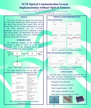
Scheme to analyze/monitor POX signals on LHO 2k IFO Evan Goetz (SURF), Dick Gustafson, Rick Savage, Paul Schwinberg. Local Oscillator. Idealized Optical Cavity Output. Carrier 3e14 Hz. Amplitude. Amplitude. SB 1- 3e14 - 30e6. SB 1+ 3e14 + 30e6. SB 2- 3e14 - 60e6. Carrier 3e14 Hz.

E N D
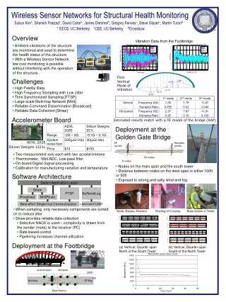
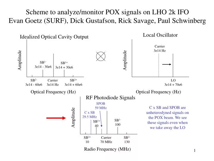
Scheme to analyze/monitor POX signals on LHO 2k IFO Evan Goetz (SURF), Dick Gustafson, Rick Savage, Paul Schwinberg Local Oscillator Idealized Optical Cavity Output Carrier 3e14 Hz Amplitude Amplitude SB1- 3e14 - 30e6 SB1+ 3e14 + 30e6 SB2- 3e14 - 60e6 Carrier 3e14 Hz SB2+ 3e14 + 60e6 LO 3e14 + 70e6 Optical Frequency (Hz) Optical Frequency (Hz) RF Photodiode Signals SPOB 59 MHz Amplitude C x SB and SPOB are unheterodyned signals on the POX beam. We see these signals even when we take away the LO C x SB 29.5 MHz SB1- 100 SB1+ 40 SB2+ 10 Carrier 70 MHz SB2- 130 Radio Frequency (MHz)
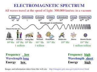
Heterodyne optical signal with shifted optical carrier • Work on ISCT 9 (2k IFO) • Shift sample of laser beam on PSL with 70 MHz AOM and couple into optical fiber • Transported beam via fiber to table 9 • Reform beam and match beams to beat on a New Focus 1811 RFPD • Study RF results with RF analyzer or 3-5 channel dedicated receivers and drive DAQ
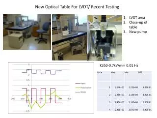
Layout Schematic DAQ 59 MHz (SPOB) 40.5 MHz (HSB) 70 MHz (CAR) 99.5 MHz (LSB) 100 m Fiber MIT Fiber Coupler Table 9 POB New Focus RFPD PSL MIT Fiber Coupler RF Analyzer AOM POX beam Test beam Laser IFO
Tests/Successes • Shifted beam frequency using 70 MHz AOM • Captured shifted beam in 3m and 100m of fiber (~50% coupling efficiency) • Reformed spatial beam from fiber • Beat with test carrier with 68.8 MHz sidebands • Efficiency ~10% (AC/DC) • Studies and tests of matching and efficiency
Tests/Successes (Cont…) • Designed and built dedicated RF receivers down-convert to either 100 Hz or 1 kHz • Designed and implemented RMS to DC conversion for the DAQ (4 256 Test channels) • Simple diode scheme, Average/ABS value scheme, or True RMS IC chips • Fed 100 Hz AC signal to DAQ (study with DTT) • 1 kHz RMSDC to DAQ (view with DV) • Observations/measurements from Control Room and offline
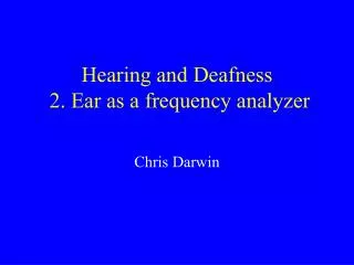
RF Down-conversion IFR 70 MHZ RF Amplifier Mixer 70.001 MHz (70.0001 MHz) 1 kHz (100 Hz) SR560 1 kHz (100 Hz) DAQ
RMS to DC • OK Out (DC) In (ACrms) • Best! Out (DC) In (ACrms)
Summary • Heterodyned POX Recycling Cavity beam to separate channels for RF display • Converted RMS to DC into DAQ for monitor/study/analysis • Unique RMS amplitude measures of LSB, HSB, CAR, unheterodyned SPOB (phase independent), unheterodyned SB x C. • DC or 100 Hz AC can use 256 channels
Summary (Cont…) • Table 9 for 2k POX, Table 3 for 4k POX • Relatively available, non-invasive • No ground loops • PSL: • AOM—no ground loops • Back side is available for module