Download
1 / 20
210 likes | 414 Views
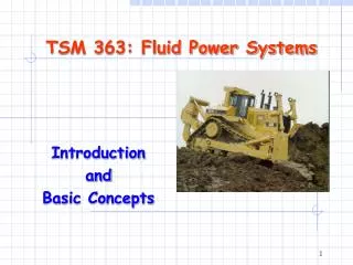
TSM 363 Fluid Power Systems. Hydrostatic Transmission. Hydrostatic Transmission is popular in ORE. Mechanical Drivetrain. A mechanical drivetrain system consists of an engine, a clutch, a transmission, a universal drive- line, a differential, and the wheels.

E N D
TSM 363 Fluid Power Systems Hydrostatic Transmission
Mechanical Drivetrain • A mechanical drivetrain systemconsists of an engine, a clutch,a transmission, a universal drive-line, a differential, and the wheels. • Transmission is used to increaseor decrease speed • A differential is needed inmechanical drivetrain, becauseit allows the outside wheel torotate faster than in the insidewheel when the vehicle turns.
Hydrostatic Transmission Drivetrain • With a hydrostatic transmission, itconsists of an engine, a clutch,a hydrostatic transmission, a universal driveline, a differential, and the wheels. • Change the displacement of thepump (or motor) can change the vehicle speed. • HT improves maneuverability: > wide range of T/n ratio > compacted, less mass inertia > dynamic braking (inst. reverse) > able to stall & undamaged > no interruption of power • HT has lower efficiency
Basic Concept of Hydrostatic Transmission A hydrostatic transmission is simply a pump and motor(s) connected in a circuit.
C C C C (b) Variable pump-fixed motor (c) Fixed pump-variable motor (d) Variable pump-variable motor Typical Closed-Circuit HST Configurations (a) Fixed pump-fixed motor
C Typical Performance of VP-FM HST
C Typical Performance of FP-VM HST
C C Typical Performance of VP-VM HST
(b) Four-way valve controlledfixed pump-fixed motor Typical Open-Circuit HST Configurations (a) Needle valve controlledfixed pump-fixed motor
Motor speed Theoretical flow Pump flow Qt = (DP·nE)/231 = (1.925x2400)/231 = 20 gpm QP = Qt ·EffP = 20x0.90 = 18 gpm nM = (QP·231)/ DM ·EffM = (18X231)/1.925x0.90 = 1944 rpm Example: Typical Calculations of HST Suppose both the pump and the motor in a hydrostatic transmission have disp. DM = 1.925 in3/rev, and the volumetric efficiency are 0.90 for both the pump and motor. The pump is driven by an engine at 2400 rpm, what is the motor speed?
Lecture Summary • Discussed the basic concepts of HST: • Closed-circuit HST: FP-FM; VP-FM; FP-VM; VP-VM • Open-circuit HST • Applications of HST: • In-line design • Sprit design • V-controlled design • Sprit-torque design