Download
1 / 15
150 likes | 154 Views
This presentation highlights two distinct HV stability problems affecting the electron beam energy, along with a simplified Spice model and potential solutions. It includes data, voltage variations, and a discussion on feedback loop and voltage readback signals.

E N D
LEReC HV supply issues and suggested solutions P. Thieberger, Z. Altinbas, D. Bruno, R. Lambiase, C. Mi, T. Miller, K Mernick, J. Sandberg and C. Schultheiss.
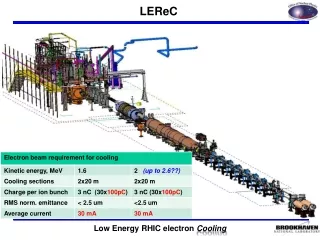
There are two distinct HV stability problems that affect the energy of the electron beam from the gun: Large, periodic, HV ripple at operating beam currents above ~10mA. Large, mostly non-periodic voltage instabilities at a few mA Attempts to solve 2) led a to a reduction of the gain-bandwidth product of the feedback loop which made 1) worse. The following slides illustrate these issues, present a simplified Spice model and suggest some possible solutions.
Data obtained at 375 kV and 21 mA beam current SIGNAL SATURATED 500 V !66 kHz 8 kV HV variations measured with the CPU system. The amplitude is ± ~4 kV. HV variations calculated from the measured inverter current numerically rectified and integrated. This means that the inverter + multiplier can be simulated as a linear voltage controlled current source. Voltage readback signal obtained by applying an 166 kHz numerical notch filter to the raw data shown on the next slide
Raw readback signal from the voltage divider not used for regulation. The 83 kHz noise is probably due to flux leakage from the ferrite core, picked up by the resistor chain. 83 kHz Readback signal after a 166 notch filter was applied to signal above
Raw signal from the inverter current transformer. Gun potential variations calculated by numerically rectifying and integrating the above data
DATA FROM THE LOCAL SCOPE @ 375kV an 16 mA beam current 120 Hz The voltage readback on the gun-side is much less noisy, as expected. No 166 KHz filtering is required The 360 Hz inverter bus ripple is not responsible for most of the large HV fluctuations which have a strong 120 Hz component. A power supply in the inverter is more likely to be the cause. 360 Hz
Simplified Spice model not including the low-current non-linearities (yet) Open-loop frequency response.
HV response to a 20 MB gap at 19 mA electron beam current measured with the CPU and simulated with the Spice model. There is good agreement in amplitude (200 V) and shape.
Voltage instability at 4 mA beam current, probably related to the fact that the multiplier can only deliver negative charge to the HV terminal. Iintegrator saturated 88.5 kV 43 ms
Comments • The HV multiplier stack response to inverter phase modulation is fast. It is not the cause of the instabilities. Modifying the stack is not likely to be very helpful. The inverter and multiplier combination have been simulated as a simple voltage-controlled current source. • One of the problems with regulation is a noisy voltage readback signal used for the feedback. • The voltage readback at the gun-side is less noisy. • An additional problem is the slow response of the feedback network probably necessitated by the need to avoid instabilities at small beam currents. • The compensation of the voltage divider may be incorrect due to the ring-to-tank capacitances. These capacitances need to be measured. • Most of the large voltage excursions at high beam currents are at 120 Hz and harmonics. This distinct from instabilities that have been observed at various frequencies and are generally non-periodic. The 120 Hz noise is likely related to a full-wave single-phase rectifier in a power supply. That power supply may be in the controller. Another possibility is that the laser intensity is slightly modulated at 120 Hz.
Suggested actions • Use a notch filter to attenuate the 166 kHz readback noise and/or: • Use a voltage divider on the gun-side which is less noisy. • Check and if necessary correct the compensation of the voltage dividers. • Consider the possibility of combining the CPU signal with the readback signal to achieve better frequency response and less noise. • Find and eliminate the source of the large 120 Hz HV fluctuations, in addition to fixing the excessive 360 Hz ripple on the inverter bus. • The implementation of the new gun-side voltage-divider should help both the readback signal quality as well as the low current instabilities. • Consider using a remotely controlled PID controller in place of the difference amplifier and its associated circuitry. This would allow us to adjust time constants dynamically to avoid instabilities at low beam intensities and to optimize regulation at high intensities. • A possible alternative to g) is to use the present system at low beam intensities and then remotely connect the CPU signal to provide more gain at the higher frequencies when the beam intensity is sufficiently large. • Verify and continue refining the SPICE model to generate better guidance for solving the regulation issues, the possible incorporation of the CPU signal and, hopefully, the instability problems.