Download
1 / 16
170 likes | 350 Views
High gradient tests with beam loaded accelerating structure. I. Syratchev. Introduction. U nloaded. CLIC nominal. Increasing current. Loaded (CLIC). Gradient along the structure. Unloaded.

E N D
High gradient tests with beam loaded accelerating structure. I. Syratchev
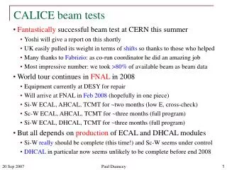
Introduction Unloaded CLIC nominal Increasing current Loaded (CLIC) Gradient along the structure Unloaded Testing of accelerating structure with nominal beam loading was a missing block in our testing program. Such a test will be done using CTF3 (1.2 A) drive beam and RF power delivered from X-box1 (90 MW) via modified 30 GHz low loss transfer line (60MW). The main target of this experiment is to compare loaded and unloaded accelerating structure breakdown trip rate.
Accelerating gradients achieved in tests. Status: 4-9-2012 loaded
Location of the Dog-leg experiment structure Beam dog-leg Former 30 GHz RF transfer line X-box1
Structure under test: CERN’s T24 (12WNDSvg1.8 KEK N1) No damping
Dog-leg experiment phase #1 (beam only) Drive beam, 1-3A, 100-50 MeV • Main objective of this phase: • To establish routine beam transportation through the structure without losses. • To integrate RF signal acquisition and the beam control systems.
Dog-leg experiment phase #1. Current status. T24 is installed in dog-leg… IN Port 1, -48.6 dB Port 4, -49.1 dB OUT Port 3, -49.1 dB Port 2, -48.7 dB Beam direction
…and calibrated -49.32 -52.04 Insertion losses of the input/output waveguide network (splitter and bends) is -0.15 dB (=0.967)
XBOX#1 Breakdown (fast) RF channels acquisition Wave forms (slow) (slow) Vacuum interlocks Ip#1 Ip#2 CTF3 Load#2 Load#2 #4 #1 Dir. coupler#2 Dir. coupler#1 Beam optic #3 #2 BPM/I #1 BPM/I #2 Beam Accelerating structure Gun beam losses Gun control Gun control This test will be fully operated from CTF3 CR and run in parallel with XBOx#1 test stand. The RF breakdown will be defected by comparing 3 sequent signals in channel #3, reflected signal in channel #2 and vacuum measurements (no Faraday cups or similar).
Beam Optics Design (F. Tecker) • Beam current 1A (CLIC main beam) => energy ~100MeV(no change of the RF pulse compression) • Line re-matched for higher beam energy with waist in the accelerating structure – done by Mohsen Dayyani Kelisani • collimator position optimized wrt. beam size • sufficient clearance in the accelerating structure accelerating structure accelerating structure Vertical beam size Dispersion function Vertical beta function Horizontal beam size Horizontal beta function dogleg bends dogleg bends 10
Beam Commissioning (F. Tecker) • Rescale linac quadrupole currents for higher energy • Measure final energy and Twiss parameters on girder 10 • Rematch linac and dogleg optics to design • Setup at 1 Hz (need new pulse compression setup if >10Hz later) • Initial structure conditioning by beam pulse length energy measurement structure Beam dog-leg Twiss measurement Former 30 GHz RF transfer line X-box1
Dog-leg experiment phase #1. Experimental program. RF peak power generated by beam at the structure output RF power profiles along the structure (100 MV/m unloaded) Processing (RF breakdowns expected) >30 MV/m last cells Klystron driven 100 MV/m last cell Power at 100 MV/m unloaded Power at 100 MV/m loaded Beam driven (2.7 A) Nominal current When compared with klystron driven tests, accelerating structure testing with beam opens unique opportunity to process only downstream part of the structure. To get meaningful results from this test, few hundred hours (>300) should be allocated.
Dog-leg experiment phase #2 XBOX#1 power source connected to accelerating structure in CTF3 linac tunnel via 18 meters of low loss waveguide network. RF power from XBOX#1 CTF2 XBOX#1 test stand
Complete Dog-leg test RF network layout (calculated RF transfer efficiency ~0.75) Mode converter type#2 RF 50 mm circular waveguide Beam The number of 12 GHz new RF components were fabricated by CERN and CEA to re-adjust ‘old’ 30 GHz low losses transfer line to the new frequency.
New RF components (closer view) H10-> H01 mode converters and tapers #1 (CEA) RF/vacuum gate valve and pumping port Compact RF pumping port with high vacuum conductivity. H10-> H01 Jog mode converters #2 (CEA)
Tentative Planning • Phase 1: • Accelerating structure installation in CTF3 dog-leg area (done). • Available for testing with drive beam. Weeks 6-20. • Phase 2: • RF transfer line modification. Weeks 21-22. • Structure processing with klystron. Week 29 onwards. • Operation in beam loaded mode can be started at week 35.