Download
1 / 33
330 likes | 443 Views
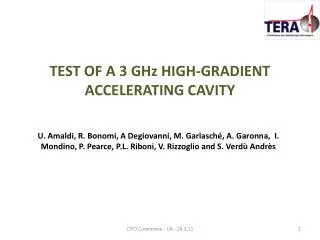
High-gradient proton accelerating structure developments at CERN. Alexej Grudiev 6/02/2014 CLIC14 Workshop. Acknowledgements.

E N D
High-gradient proton accelerating structure developments at CERN Alexej Grudiev 6/02/2014 CLIC14 Workshop
Acknowledgements • This work is done in close collaboration between CERN (M. Garlasche, A. Grudiev, I. Syratchev, M. Timmins, W. Wuensch) and TERA foundation (U. Amaldi , S. Benedetti, A. Degiovanni, P. Magagnin, G. Porcellana) in the frame work of the CERN Knowledge Transfer (KT) Fund project: “High-gradient Accelerating Structure for Proton Therapy Linacs”
Outline • Introduction • RF cavities constraints for hadrontherapy • Backward travelling wave cell design and optimization for high gradient operations • Nose cone study • Tapering • Couplers • Comparison of different structure designs • SW SCL design • backward TW • Engenearing design • Conclusions
TULIP 2.0 at 3 GHz with E0≅50 MV/m new 3 GHz bwTW structure 60 MeV 11m 5-6 m ≤ 230 MeV 3 GHz SCDTL ENEA 5 MeV 750 MHz RFQ CERN TULIP - UA - 6.3.14
Linac layout and BDR requirements • Quasi-periodic PMQ FODO lattice sets a limit to the length of each structure and determines the group velocity range. • The cells in each structure (tank) have the same length, while from one tank to the next, the cell length increases: β tapering in the range 0.22-0.60 • Trade-off between transverse acceptance and RF efficiency: bore aperture = 5 mm • Max BDR: 1 BD per treatment session (~ 5 min) on the whole linac length (~ 10 m). BDR ~ 10-6 bpp/m ...
Comparison between TW structure and SCL Tapered structures: the coupling holes are smaller along the structure Geometry of LIBO structure
Comparison of E-field in TW and SW π/2 phase advance 2/3 π phase advance
waveguide accelerating cavities coupling cavities PROs and CONs of bTW compared to standard SCL design
Proposal for bTW design for hadrontherapy P_wall DESIGN GOAL and CONSTRAINTS Ea:= E0T ≥ 50 MV/m Sc/Ea2 < 7 10-4 A/V L P_0 P_load z with: Sc < 4 MW/mm2 tTERA = 2500 ns • tCLIC = 200 ns • BDRTERA = BDRCLIC = 10-6 bpp/m Proposed by A. Grudiev vg_in ~ 0.4% c vg_out ~ 0.2% c filling time ~ 0.3 µs
Nose geometry optimization half gap • Scan on: • Nose cone angle • Gap • Nose cone radius(*) • Phase advance (120°-150°) • coupling hole radius (vg = 4 ‰ and 2 ‰ ) • Optima: • Minimum of the quantity: noseradii nose angle septum bore radius * based also on results of the SCL optimization
Optimization plots vg [10-3 c] R’/Q [Ω/m] Sc/Ea2 [10-3Ω-1]
150° - 16 holes – nose 1 -2 mm – gap and angle scan g 7.0 mm A 55 deg g 7.0 mm A 55 deg
150° - 16 holes – nose 1 -2 mm – gap and angle scan g 7.0 mm A 55 deg g 7.0 mm A 55 deg
Tank optimization • Minimization of the SW pattern by adjusting the out-coupler • Final optimization of the in-coupler to get the final design of the tank
RF design of the full structure isdone The Sc/Ea^2 < 7e-4 A/V constraint is respected
Backward travelling wave accelerating structure Cooling plates Accelerating elements
Acceleratingstructure 150° of phase advance 4 holes for dimpler tuners
Joining procedures Hydrogen Bonding: THB=1050 °C Gold Brazing: TGB=950 °C Silver Brazing: TSB=820 °C OFE Copper melting point 1083 °C CREEP?
Evaluation of different cells structural performance 150° of phase advance 120° of phase advance Load: gravitational force g g
Creeptests 20 discs, to be tested at the 3 temperatures, in order to simulate vertical and horizontal bonding/brazing. S = 2 mm
Creep Results in general - Summary H V H V H V Average Axial: 13 μm ; Average Radial: 6 μm (withoutcells 2 and 8) 10
Summary • Optimization of TW structures for high gradient operations has been performed for 120° and 150° phase advance. • 150° phase advance has been chosen • The RF design of the input and output coupler is finished. • Creep tests have been performed to validate H-bonding at 1050 ° C • The Engenering design including thermo-mechnical simulation is progressing well • The design and test of the novel bTW structures is boosting the TULIP project!
High-Gradient RF Test Stand plans at IFIC IFIC-IFIMED, Valencia CLIC Workshop 2014 3-7 February 2013 A. Faus-Golfeon behalf of IFIC, GAP (Group of Accelerator Physics) http://gap.ific.uv.es Valencia, Spain
Framework • The IFIMED: Research on Imaging and Accelerators applied to Medicine. • As an R&D Institute on Medical Physics it is configured through two Research • Groups: • Image Science: New Imaging devices as Compton combined with Positron Emission (PET) in the context of the ENVISION project, as well as the development and design of the reconstruction algorithms • Accelerators: Linacs for medical applications as cyclinacs (S and C-bands) in the context of PARTNER project in collaboration with TERA and Beam Instrumentation for hadrontherapy
Objectives • In the framework of the KT project:“High Gradient Accelerating Structures for proton therapy linacs”, whose scope is the design, construction and high power test of two high-power prototype 3 GHz accelerating structures at 76 MeV (low energy) and 213 MeV (high energy) which corresponds to the to the lowest and highest energy of the proton linac. • The idea is to complement these studies with the design and test of two intermediate (2nd and 3rd) proton linac structures. This complementary study will give us the possibility to simulate the most realistic conditions and running operation conditions of this kind of linacs. • Test stand with two klystrons (3GHz have 7.5 MW power each, 5 ms RF pulse duration and 400 Hz), the RF system becomes much more flexible allowing arbitrary phase and amplitude pulse shapes even when using a pulse compressor.
Location IFIMED R&D labs integrated in the Scientific Park of the UV RF and Instrumentation labs