Download
1 / 45
1.34k likes | 3.39k Views
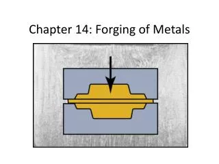
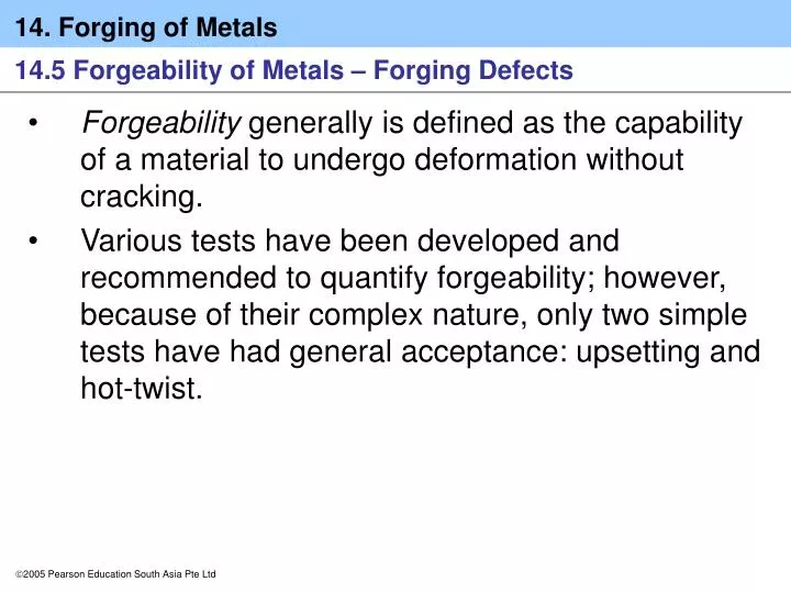
14.5 Forgeability of Metals – Forging Defects. Forgeability generally is defined as the capability of a material to undergo deformation without cracking.

E N D
14.5 Forgeability of Metals – Forging Defects • Forgeability generally is defined as the capability of a material to undergo deformation without cracking. • Various tests have been developed and recommended to quantify forgeability; however, because of their complex nature, only two simple tests have had general acceptance: upsetting and hot-twist.
14.5 Forgeability of Metals – Forging Defects • In the upsetting test, a solid, cylindrical specimen is upset between flat dies, and the reduction in height at which cracking on the barreled surfaces begins is noted. • The forgeability of various metals and alloys is given in Table 14.3 in decreasing order.
14.5 Forgeability of Metals – Forging Defects Forging Defects • In addition to surface cracking during forging, other defects also can develop as a result of the material flow pattern in the die. • Fig 14.16 shows examples of defects in forged parts. (a) Laps formed by web buckling during forging; web thickness should be increased to avoid this problem. (b) Internal defects caused by an oversized billet. Die cavities are filled prematurely, and the material at the center flows past the filled regions as the dies close.
14.5 Forgeability of Metals – Forging Defects Forging Defects • Internal defects also may develop from (a) nonuniform deformation of the material in the die cavity, (b) temperature gradients throughout the workpiece during forging, and (c) microstructural changes caused by phase transformations.
14.6 Die Design, Die Materials, and Lubrication • The design of forging dies requires considerable knowledge and experience regarding the shape and complexity of the workpiece, its ductility, its strength and sensitivity to deformation rate and temperature, and its frictional characteristics. • With continuing advances in developing reliable simulation of all types of metalworking operations, software is available to help predict material flow in forging die cavities under various conditions such as temperature and heat transfer, frictional conditions at die-workpiece contact surfaces, and forging speed.
14.6 Die Design, Die Materials, and Lubrication Preshaping • In a properly preshaped workpiece, the material should not flow easily into the flash (as otherwise die filling will be incomplete), the grain flow pattern should be favorable for the products’ strength and reliability, and excessive sliding at the workpiece–die interfaces should be minimized in order to reduce die wear. • Computer modeling and simulation techniques are very useful in such calculations.
14.6 Die Design, Die Materials, and Lubrication Die design feature • For most forgings, the parting line is at the largest cross-section of the part. • For simple symmetrical shapes, the parting line is normally a straight line at the center of the forging, but for more complex shapes, the line may not lie in a single plane. • After sufficiently constraining lateral flow to ensure proper die filling, the flash material is allowed to flow into a gutter, so that the extra flash does not increase the forging load unnecessarily.
14.6 Die Design, Die Materials, and Lubrication Die design feature • Draft angles are necessary in almost all forging dies in order to facilitate the removal of the part from the die. • Selection of the proper radii for corners and fillets is important in order to ensure smooth flow of the metal into the die cavity and to improve die life.
14.6 Die Design, Die Materials, and Lubrication Die materials • Most forging operations (particularly for large parts) are carried out at elevated temperatures. • General requirements for die materials therefore are • Strength and toughness at elevated temperatures. • Hardenability and ability to harden uniformly.
14.6 Die Design, Die Materials, and Lubrication Die materials • General requirements for die materials therefore are • Resistance to mechanical and thermal shock. • Wear resistance (particularly resistance to abrasive wear) because of the presence of scale in hot forging.
14.6 Die Design, Die Materials, and Lubrication Lubrication • Lubricants greatly influence friction and wear. • Consequently, they affect the forces required and the manner in which the material flows into the die cavities.
14.7 Die Manufacturing Methods – Die failures • Several manufacturing methods, either singly or in combination, can be used to make dies for forging as well as for other metalworking processes. • These processes include (a) casting, (b) forging, (c) machining, (d) grinding, (e) electrical and electrochemical methods—particularly electrical-discharge machining (EDM) and wire EDM—and (f) lasers for small dies. • An important and continuing development is the production of tools and dies by rapid tooling using rapid protoyping techniques.
14.7 Die Manufacturing Methods – Die failures • The process of producing a die cavity in a die block is called die sinking. • The choice of a die manufacturing method depends on its size and shape and the particular operation in which the die is to be used, such as casting, forging, extrusion, powder metallurgy, and plastics molding. • Most commonly, dies are machined from forged die blocks by processes such as high-speed milling, turning, grinding, and electrical discharge and electrochemical machining.
14.7 Die Manufacturing Methods – Die failures • After using heat treatment to achieve the desired mechanical properties, dies usually are subjected to finishing operations, such as grinding polishing, and chemical and electrical processes, to obtain the desired surface finish and dimensional accuracy.
14.7 Die Manufacturing Methods – Die failures Die cost • From the preceding discussion, it is evident that the cost of a die will depend greatly on its size, shape complexity, application, and the surface finish required, as well as the die material and manufacturing, heat treating, and finishing methods employed.
14.7 Die Manufacturing Methods – Die failures Die failures • Failure of dies in manufacturing operations generally results from one or more of the following causes: • Improper die design • Defective or improper selection of die material • Improper manufacturing and improper heat-treatment and finishing operations • Overheating and heat checking (i..e., cracking caused by temperature cycling)
14.7 Die Manufacturing Methods – Die failures Die failures • Failure of dies in manufacturing operations generally results from one or more of the following causes: • Excessive wear • Overloading (i.e., excessive force on the die) • Improper alignment of the die components with respect to their movements • Misuse • Improper handling of the die
14.8 Forging Machines • A variety of forging machines are available with a range of capacities (tonnage), speeds, and speed-stroke characteristics (Table 14.4).
14.8 Forging Machines Hydraulic presses • These presses operate at constant speeds and are load limited or load restricted. • A hydraulic press typically consists of a frame with two or four columns, pistons, cylinders, rams, and hydraulic pumps driven by electric motors. • Fig 14.17 shows the schematic illustration of the principles of various forging machines. (a) Mechanical press with an eccentric drive; the eccentric shaft can be replaced by a crankshaft to give the up-and-down motion to the ram. (b) Knuckle-joint press. (c) Screw press. (d) Hydraulic press.
14.8 Forging Machines Mechanical presses • These presses are basically of either the crank or the eccentric type. • The speed varies from a maximum at the center of the stroke to zero at the bottom of the stroke, thus they are stroke limited. • The force available in a mechanical press depends on the stroke position and becomes extremely high at the bottom “dead” center. • Thus, proper setup is essential to avoid breaking the dies or equipment components.
14.8 Forging Machines Screw presses • These presses derive their energy from a flywheel; hence, they are energy limited. • The forging load is transmitted through a large vertical screw, and the ram comes to a stop when the flywheel energy is dissipated.
14.8 Forging Machines Hammers • Hammers derive their energy from the potential energy of the ram, which is converted into kinetic energy; hence, they are energy limited. • Unlike hydraulic presses, hammers (as the name implies) operate at high speeds, and the resulting low forming time minimizes the cooling of a hot forging.
14.8 Forging Machines Drop hammers • In power drop hammers, the ram’s downstroke is accelerated by steam, air, or hydraulic pressure at about 750 kPa. • In the operation of gravity drop hammers (a process called drop forging), the energy is derived from the free-falling ram (potential energy).
14.8 Forging Machines Counterblow hammers • This hammer has two rams that simultaneously approach each other horizontally or vertically to forge the part. • As in open-die forging operations, the part may be rotated between blows for proper shaping of the workpiece during forging.
14.8 Forging Machines High energy rate forging (HERF) machines • In this type of machine, the ram is accelerated rapidly by inert gas at high pressure, and the part is forged in one blow at a very high speed.
14.9 Economics of Forging • Depending on the complexity of the forging, tool and die costs range from moderate to high. • Fig 14.18 shows the Typical (cost-per-piece) in forging; note how the setup and the tooling costs-per-piece decrease as the number of pieces forged increases if all pieces use the same die.
14.9 Economics of Forging • The ratio of the cost of the die material to the total cost of forging the part increases with the weight of forgings; the more expensive the material, the higher the cost of the material relative to the total cost. • The size of forgings also has some effect on cost. Sizes range from small forgings (such as utensils and small automotive components) to large ones (such as gears and crankshafts and connecting rods for large engines).
14.9 Economics of Forging • The total cost involved in a forging operation is not influenced to any major extent by the type of materials forged. • The cost of forging a part compared to that of making it by various casting techniques, powder metallurgy, machining, or other methods is an important consideration in a competitive global marketplace. • Fig 14.19 shows the relative unit costs of a small connecting rod made by various forging and casting processes. Note that, for large quantities, forging is more economical. Sand casting is the most economical process for fewer than about 20,000 pieces.
Case Study 14.2 Suspension components for the Lotus Elise automobile The automotive industry increasingly has been subjected to a demanding set of performance, cost, fuel efficiency, and environmental regulations. One of the main strategies in improving vehicle design with respect to all of these (seemingly) contradictory constraints is to reduce vehicle weight while using advanced materials and manufacturing processes to preserve performance and safety. Previous design optimization has shown that weight savings of up to 34% could be realized on suspension system components, which is significant since suspensions make up approximately 12% of a car’s mass.
Case Study 14.2 Suspension components for the Lotus Elise automobile These weight savings could be achieved largely by developing optimum designs, using advanced analytical tools, and using netshape or near-net shape steel forgings instead of cast-iron components. In addition, significant cost savings have been demonstrated in many parts when using optimized steel forgings compared to aluminum castings and extrusions.
Case Study 14.2 Suspension components for the Lotus Elise automobile The Lotus Elise is a high-performance sports car designed for superior ride and handling. The Lotus group investigated the use of steel forgings instead of extruded- aluminum suspension uprights in order to reduce cost and improve reliability and performance. Their development efforts consisted of two phases, as shown in Fig. 14.20. The first phase involved the development of a forged-steel component that can be used on the existing Elise sports car; the second phase involved the production of a suspension upright for a new model.
Case Study 14.2 Suspension components for the Lotus Elise automobile A new design was developed using an iterative process with advanced software tools to reduce the number of components and to determine the optimum geometry. The material selected for the upright was an air-cooled forged steel, which gives uniform grain size and microstructure and uniform high strength without the need for heat treatment. These materials also have approximately 20% higher fatigue strengths than traditional carbon steels, such as AISI 1548-HT, which is used for similar applications.
Case Study 14.2 Suspension components for the Lotus Elise automobile The revised designs are summarized in Table 14.5. As can be seen, the optimized new forging design (Fig 14.20d) resulted in significant cost savings. Although it also resulted in a small weight increase when compared to the aluminum-extrusion design, the weight penalty is recognized as quite small, and the use of forged steel for such components is especially advantageous in fatigue-loading conditions constantly encountered by suspension components.
Case Study 14.2 Suspension components for the Lotus Elise automobile The new design also had certain performance advantages in that the component stiffness is now higher, which registered as improved customer satisfaction and better “feel” during driving. Furthermore, the new design reduced the number of parts required, thus satisfying another fundamental principle in design.
Case Study 14.2 Suspension components for the Lotus Elise automobile
Case Study 14.2 Suspension components for the Lotus Elise automobile
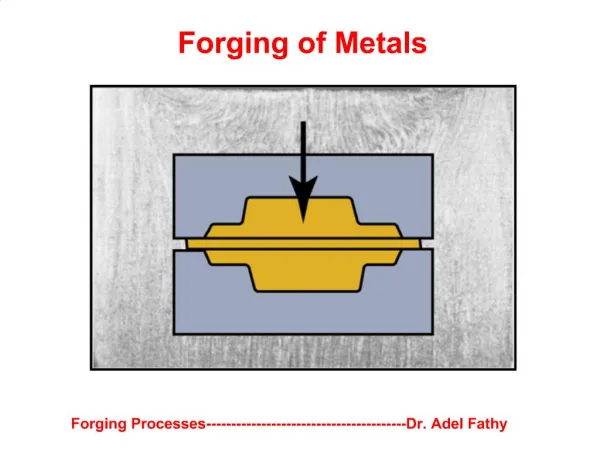
Concept Summary • Forging denotes a family of metalworking processes in which deformation of the workpiece is carried out by compressive forces typically applied through a set of dies. Forging is capable of producing a wide variety of structural parts with favorable characteristics, such as strength, toughness, dimensional accuracy, and reliability in service.
Concept Summary • The forging process can be carried out at room, warm, or high temperatures. Workpiece material behavior during deformation, friction, heat transfer, and material-flow characteristics in the die cavity are important considerations, as are the proper selection of die materials, lubricants, workpiece and die temperatures, forging speeds, and equipment.
Concept Summary • Various defects can develop if the forging process is not controlled properly, especially in workpiece quality, billet or preform shape, and die geometry. Computer aided design and manufacturing techniques now are used extensively in die design and manufacturing, preform design, predicting material flow, and in avoiding the possibility of internal and external defects during forging.
Concept Summary • A variety of forging machines are available, each with its own capabilities and characteristics. Forging operations are now highly automated by using industrial robots and computer controls. • Swaging is a type of rotary forging in which a solid rod or a tube is reduced in diameter by the reciprocating radial movement of a set of two or four dies. The process is suitable for producing short or long lengths of bar or tubing with various internal or external profiles.
Concept Summary • Because die failure has a major economic impact, die design, material selection, and production method are of major importance. A variety of die materials and manufacturing methods are available, including advanced material-removal and finishing processes.