Download
1 / 49
771 likes | 1.94k Views
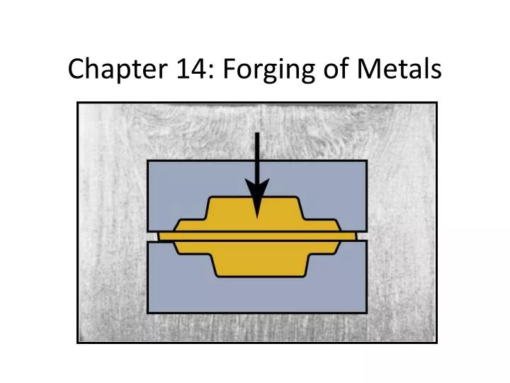
Chapter 14: Forging of Metals. 14.1 Introduction. Forging: a Process in which the work-piece is shaped by compressive forces applied through various dies and tools. Typical forged products: bolts, rivets, connecting rods, shafts for turbines, gears, hand tools, etc...

E N D
14.1 Introduction • Forging: a Process in which the work-piece is shaped by compressive forces applied through various dies and tools. • Typical forged products: bolts, rivets, connecting rods, shafts for turbines, gears, hand tools, etc... • Figure 14.3 shows a part made by 3 different processes: (a) casting, (b) machining, (c) forging
14.1 Introduction • Cold forged parts have good surface finish and dimensional accuracy. • Hot forging requires smaller forces, but it produces dimensional accuracy and surface finish that are not as good as in cold forging.
14.2 Open die forging • Most open-die forgings generally weigh 15-500 Kg, forgings as heavy as 275 tons have been made. • Sizes may range from very small parts (nails, pins, and bolts)up to 23 m for ships shafts. • Upsetting or flat-die forging (Fig. 14.3): The die surfaces in open-die forging may have simple cavities, to produce relatively simple forgings.
14.2 Open die forging Figure 14.3: (a) Ideal deformation of a solid cylindrical specimen compressed between flat frictionless dies, an operation known as upsetting. (b) Deformation in upsetting with friction at the die-workpiece interfaces. Note barrelling of the billet caused by friction.
14.2 Open die forging • Barreling is caused primarily by frictional forces at the die-work-piece interfaces that oppose the outward flow of the materials at these interfaces. Barreling can be minimized by using an effective Lubricant. • Barreling can also occur in upsetting hot work-pieces between cold dies. The material at and near the interfaces cools rapidly, while the rest of the work-piece remains relatively hot. Thus, the material at the ends of the work-piece has higher resistance to deformation than the material at its center. Consequently, the central portion of the work-piece expands laterally to a greater extent than do its ends. • Barreling from thermal effects can be reduced or eliminated by using heated dies.
14.2 Open die forging -cogging • Cogging (drawing out): an open-die forging operation in which thickness of a bar is reduced by successive forging steps at specific intervals. Because contact area per stroke is small, a long section of a bar can be reduced in thickness without requiring large forces or machinery
14.2 Open die forging -cogging Figure 14.4: (a) Schematic illustration of a cogging operation on a rectangular bar. Blacksmiths use a similar procedure to reduce the thickness of parts in small increments by heating the workpiece and hammering it numerous times along the length of the part. (b) Reducing the diameter of a bar by open-die forging; note the movements of the die and the workpiece. (c) The thickness of a ring being reduced by open-die forging.
14.2 Open die forging • The forging force, F, in an open-die forging operation on a solid cylindrical piece: • Yf: flow stress of the material, stress required to continue plastic deformation of the work-piece at a particular true strain. • µ :coefficient of friction, • r andh: radius and height of the work-piece • example
14.2 Open die forging • Example14.1: A solid cylindrical slug made of 304 stainless steel is 150 mm in diameter and 100 mm high. It is reduced in height by 50% at room temperature by open-die forging with flat dies. Assuming that the coefficient of friction is 0.2, calculate the forging force at the end of the stroke.
14.3 impression-die and closed-die forging • In impression-die forging, the work-piece acquires the shape of the die cavities while being forged between two shaped dies (Fig. 14.5). • The thin flash cools rapidly, and because of its frictional resistance, it subjects the material in the die cavity to high pressures, thereby encouraging the filling of the die cavity.
14.3 impression-die and closed-die forging • FIGURE I4.5 (a) through (c) Stages in impression-die forging of a solid round billet. Note the formation of flash, which is excess metal that is subsequently trimmed off. (d) Standard terminology for various features of a forging die
14.3 impression-die and closed-die forging • Pre-forming processes, such as fullering and edging (Figs.14.7b and c), are used to distribute the material into various regions of the blank. • In fullering material is distributed away from an area. • In edging, it is gathered into a localized area. • The part is then formed into the rough shape of a connecting rod by a process called blocking, using blocker dies. • The final operation is the finishing of the forging in impression dies that give the forging its final shape. The flash is removed later by a trimmingoperation.
14.3 impression-die and closed-die forging • The blank is placed on the lower die and, as the upper die begins to descend, the blank’s shape gradually changes, as is shown for the forging of a connecting rod in fig. 14.7a.
14.3 impression-die and closed-die forging • The forging force, F, required to carry out an impression-die forging operation can be estimated from the formula F = KYfA • K: a multiplying factor (Table 14.2) • Yf : flow stress of material at the forging temperature, • A: is projected area of forging, including the flash.
14.3 impression-die and closed-die forging • In true closed-die or flash-less forging ,flash does not form and the work-piece completely fills the die cavity. Consequently, the forging pressure is very high, • Undersize blanks prevent complete filling of die cavity. • Oversize blanks generate excessive pressures and may cause dies to fail.
14.3.1 Precision forging • In order to reduce the number of additional finishing operations required-hence the cost-the trend has been toward greater precision in forged products (net-shape forming). • Special dies produce parts having greater accuracies than those from impression die forging and requiring much less machining. • Process requires higher capacity equipment because of greater forces required to obtain fine details on part. • Precision forging requires special and more complex dies, precise control of billet’s volume and shape, accurate positioning of the billet in die cavity, and hence higher investment. However, less material is wasted, less subsequent machining required.
14.4 Various Forging Operations- Coining • The slug is coined in a completely closed die cavity. • In order to produce fine details the pressures required can be as high as 5 or 6 times the strength of the material. • Lubricants cannot be applied in coining, because they can become entrapped in the die cavities, and being incompressible, prevent the full reproduction of die surface details. • Coining process is also used with forgings and with other products, to improve surface finish and to impart the desired dimensional accuracy. This process, called sizing, involves high pressures, with little change in part shape during sizing. Figure 14.10: Schematic illustration of the coining process
14.4 Various Forging Operations- Heading • Heading: upsetting operation usually performed at end of round rod or wire to produce a larger x-section. • Production rates: 100’s pieces per min for small parts. • Typical products are nails, bolt heads, screws, rivets, and various other fasteners(Fig. 14.11). FIGURE 14.11: (a) Heading operation to form heads on fasteners, such as nails and rivets. (b) Sequence of operations used to produce a typical bolt head by heading.
14.4 Various Forging Operations- Heading • Rules for upset forging: • Max Length of unsupported metal that can be upset in one blow without buckling: 3 times the diameter of bar. • lengths of stock greater than 3 times diameter may be upset successfully such that the diameter of the cavity is no more than 1.5 the diameter of the bar. • For stock length more than 3 times bar diameter and where the diameter of cavity is not more than 1.5 bar diameter, length of unsupported metal beyond the face of the die must not exceed the diameter of the bar. See Video Bolt Forging
14.4 Various Forging Operations- Piercing • Piercing: a process of indenting the surface of a work-piece with a punch in order to produce a cavity or an impression • The piercing force depends on the x-sectional area and the tip geometry of punch, strength of material, and magnitude of friction at the sliding interfaces. • The pressure may range from 3 to 5 times the strength of the material
14.4 Various Forging Operations- Hubbing • pressing a hardened punch, having particular tip geometry, into surface of a block of metal. Cavity produced is then used as a die for forming operations. • The die cavity usually is shallow, but for deeper cavities, some material may be removed from the surface by machining prior to hubbing. Hubbing force = 3(UTS)(A)
14.4 Various Forging Operations- Orbital Forging • The upper die moves along an orbital path and forms the part incrementally. • Although not in common use, typical components that may be forged by this process are disk-shaped and conical parts, such as bevel gears and gear blanks. • See Video Orbital Forging
14.4 Various Forging Operations- Isothermal Forging • Also known as hot-die forging. • In this process the dies are heated to the same temperature as that of the hot workpiece. • Because the workpieceremains hot, its ductility is maintained during forging. • The forging load is low, and material flow within the die cavity is improved. • The dies for hot forging of high temperature alloys usually are made of nickel or molybdenum alloys (because of their resistance to high temperature), but steel dies can be used for aluminum alloys. • Isothermal forging is expensive and the production rate is low. • It can be economical for specialized, intricate forgings made of materials such as aluminum, titanium, and superalloys, provided that the quantity required is sufficiently high to justify the die costs.
14.4 Various Forging Operations- RotarySwaging • also known as radial forging, rotary forging, or simply swaging) • a solid rod or tube is subjected to radial impact forces by a set of reciprocating dies of the machine (Figs. 14.14a and b). • Die movements are obtained by means of a set of rollers in a cage. • The work-piece is stationary and the dies rotate, striking the work-piece at rates as high as 20 strokes per second • In die closing swaging machines, die movements are obtained through reciprocating motion of wedges (Fig. 14.14c). • In another type of machine, the dies do not rotate, but move radially in and out. Typical products made are screwdriver blades and soldering iron tips
Swaging Figure 14.14 (a) Schematic illustration of the rotary-swaging process. (b) Forming internal profiles on a tubular workpiece by swaging. (c) A die-closing swaging machine showing forming of a stepped shaft. (d) Typical parts made by swaging. Source: Courtesy of J. Richard Industries.
14.4 Various Forging Operations- TubeSwaging • internal diameter and/or thickness of the tube can be controlled with or without use of internal mandrels (Figs. 14.15a and b). Mandrels can also be made with longitudinal grooves, to allow swaging of internally shaped tubes (Fig. 14.15c). • Swaging process can be used to assemble fittings over cables and wire. • Swaging is usually limited to max work-piece diameter of about 150 mm Figure 14.15 (a) Swaging of tubes without a mandrel; note the increase in wall thickness in the die gap. (b) Swaging with a mandrel; note that the final wall thickness of the tube depends on the mandrel diameter. (c) Examples of cross-sections of tubes produced by swaging on shaped mandrels. Rifling (internal spiral grooves) in small gun barrels can be made by this process.
14.5 Forgeabilityof Metals; Forging Defects • Forge-ability: the capability of a material to undergo deformation without cracking. • A commonly used Forge-ability tests are: 1. Upsetting test which is to upset a solid cylindrical specimen and observe any cracking on the barreled surfaces. • The greater the deformation prior to cracking, the greater the forge-ability of the metal.
14.5 Forgeabilityof Metals; Forging Defects 2. Hot-twist test • A round specimen twisted continuously in the same direction until it fails. • The test is performed on a number of specimens at different temperatures, • The number of turns that each specimen undergoes before failure is observed. • The temperature at which the maximum number of turns occurs then becomes the forging temperature for maximum forgeability. See Table 14.3. • For warm forging, temperatures range from 200 oC to 300 oC for aluminum alloys and from 550 oC to 750 oC for steels.
14.5 Forgeabilityof Metals; Forging Defects • Forging Defects: • If there is an insufficient volume of material to fill the die cavity, the web may buckle during forging and develop laps (fig. 14.16a). • If the web is thick, the excess material flows past the already formed portions of the forging and develops internal cracks. • Internal defects may also develop from non-uniform deformation of material in the die cavity, from temperature gradients throughout the work-piece during forging, and from micro structural changes caused by phase transformations.
Defects in Forged Parts Figure 14.16 Examples of defects in forged parts. (a) Laps formed by web buckling during forging; web thickness should be increased to avoid this problem. (b) Internal defects caused by an oversized billet. Die cavities are filled prematurely, and the material at the center flows past the filled regions as the die closes.
14.6 Die Design, Die Materials, and Lubrication • Considerations for die design: • The shape and complexity of the workpiece, its ductility, its strength and sensitivity to deformation rate and temperature, and its frictional characteristics • Die distortion under high forging loads. • The most important rule in die design is the fact that the part will flow in the direction of least resistance. Thus, the workpiece intermediate shapes should be planned so that they properly fill the die cavities.
14.6 Die Design, Die Materials, and Lubrication • Die Materials • General requirements for die materials are: • strength and toughness at elevated temperatures. • harden-ability and ability to harden uniformly. • resistance to mechanical and thermal shock, and Wear resistance.
14.6 Die Design, Die Materials, and Lubrication • Die Materials • Selection of proper die materials depends on: • die size, • composition and properties of work-piece, • complexity of the shape, • the forging temperature, • type of forging operation, • cost of die materials, • number of forgings required, • Heat transfer from the hot work-piece to the dies. • Common die materials are tool and die steels containing chromium, nickel, molybdenum, and vanadium.
14.6 Die Design, Die Materials, and Lubrication • Lubrication • Lubricants Act as: • A thermal barrier between the hot work-piece and the relatively cold dies, slowing the rate of cooling of the work-piece and improving metal flow. • A parting agent preventing the forging from sticking to the dies and helping release it from the die.. • For hot forging, graphite, molybdenum disulfide, are used. • For cold forging, mineral oils and soaps are common Lubricants, • in hot forging, the Lubricant is usually applied directly to the dies • In cold forging, it is applied to the work-piece.
14.7 Die-manufacturing Methods and Die Failures • The die manufacturing methods include casting, forging, machining, grinding, electrical and electrochemical methods-particularly electrical-discharge machining (EDM) and wire EDM-and the use of lasers for small dies. • The process of hubbing (Section 14.4), either cold or hot, also may be used to make small dies with shallow cavities.
14.7 Die-manufacturing Methods and Die Failures • Die Failures • Causes: • Improper die design • Defective or improper selection of die material • Improper manufacturing and improper heat-treatment and finishing operations • Overheating and heat checking (i.e., cracking caused by temperature cycling) • Excessive wear • Overloading (i.e., excessive force on the die) • Improper alignment of the die components with respect to their movements • Misuse • Improper handling of the die.
14.8 Forging Machines-Presses • Hydraulic presses: Constant speeds, load limited (press stops if the load required exceeds its capacity). Because forging in a hydraulic press takes longer than in other types of forging machines, the work-piece may cool rapidly unless the dies are heated. Compared to mechanical presses, hydraulic presses are slower and involve higher initial cost, less maintenance. • Press capacities range up to 125 MN for open die forging, and up to 405 MN.
Principles of Various Forging Machines Figure 14.17 Schematic illustration of the principles of various forging machines. (a) Mechanical press with an eccentric drive; the eccentric shaft can be replaced by a crankshaft to give the up-and-down motion to the ram. (b) Knuckle-joint press. (c) Screw press. (d) Hydraulic press.
14.8 Forging Machines-Presses • Mechanical presses: either the crank or the eccentric type. • The speed varies from max at the center of the stroke to zero at the bottom of the stroke, are stroke limited. • A Knuckle-joint mechanical press is shown in Fig. 14.21c. (see also Fig. 14.17b) because of the linkage design, very high forces can be applied in this type of press. • The Force available in a mechanical press depends on the stroke position; it becomes extremely high at the bottom dead center. • High production rates; easier to automate, less operator skill than do other types of forging machines. • Press capacities generally range from 2.7 MN (300 tons) to 107 MN (12,000 ton). • Mechanical presses are preferred for forging parts with high precision.
14.8 Forging Machines-Presses • Screw Presses: These presses (Fig. 14.17c) derive their energy from a flywheel; hence they are energy limited. • The forging load is transmitted through a vertical screw, and the ram comes to a stop when the flywheel energy is dissipated. • Suitable for small production quantities and precision parts, • Capacities range from 1.4 MN to 280 MN (160 tons to 31,500 tons).
14.8 Forging Machines-Hammers • Hammers derive their energy from the potential energy of the ram, which is converted into kinetic energy; hence, they are energy limited. • Operate at high speeds; the resulting low forming time minimizes the cooling of a hot forging. Low cooling rates allow the forging of complex shapes. • To complete the forging, several successive blows usually are made in the same die. • The least expensive type of forging equipment.
14.8 Forging Machines-Hammers • Gravity Drop Hammers: Ram weights range from 180 kg to 4500 Kg with energy capacities ranging up to 120 kJ. • Power Drop Hammers: The ram’s down stroke is accelerated by steam, air, or hydraulic pressure at about 750 kPa. • Ram weights range from 225 kg to as much as 22,500 kg, with energy capacities ranging up to 1150 kJ. • Counterblow hammers: This hammer has two rams that simultaneously approach each other horizontally or vertically to forge the part. Operate at high speeds and transmit less vibration to their bases. Capacities range up to 1200 kJ.
14.9 Economics of Forging Figure 14.18 Typical (cost-per-piece) in forging; note how the setup and the tooling costs-per-piece decrease as the number of pieces forged increases if all pieces use the same die.
14.9 Economics of Forging Figure 14.19 Relative unit costs of a small connecting rod made by various forging and casting processes. Note that, for large quantities, forging is more economical. Sand casting is the most economical process for fewer then about 20,000 pieces.