Download
1 / 16
160 likes | 316 Views
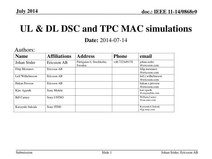
UL & DL DSC and TPC MAC simulations. Authors:. Date: 2014-07-14. Abstract.

E N D
UL & DL DSC and TPC MAC simulations Authors: • Date:2014-07-14 Johan Söder, Ericsson AB
Abstract • In this presentation we share system simulations results obtained from the evaluation of a Dynamic Sensitivity Control (DSC) mechanism (for both UL and DL) as well as results evaluating the potential of Transmission Power Control (TPC) Johan Söder, Ericsson AB
Context • DSC [1], [2] has been shown to provide performance improvements in UL • However, the majority of the traffic is still in DL direction; hence DL optimization techniques need also be considered • Transmit Power Control (TPC) is another proposed feature that shows promising results Johan Söder, Ericsson AB
Simulationscenario 2:Enterprise • “Enterprise Scenario” as defined in [3] • 8 offices, 64 cubicles per office, 2 STAs per cubicle • (8 x 64 x 2) / 32 = 32 STA/AP • 4 x 20MHz channels (8 APs on the same channel) • 32 x 8 = 256 STAs on the same channel • COST231 propagation model • Web-browsing and local file transfer AP<->STA • No P2P links included Johan Söder, Ericsson AB
Simulation assumptions • MAC layer simulator • 802.11n • Tx Power AP = 20dBm • Tx Power STA = 20dBm • Antennas AP: 2Tx, 2Rx • Antennas STA: 2Tx, 2Rx • Reference CCAT = -82dBm Johan Söder, Ericsson AB
Traffic assumptions • Files arrive independently in the buffers of the STAs(UL) and the APs (DL, files labelled with a receiver STA) • Arrival process is a Poisson process • Arrival intensity of DL and UL files has ratio 80/20 • Different system loads are modelled by varying arrival intensity, the file size is kept constant • Sample file size is 1MB Johan Söder, Ericsson AB
Johan Söder, Ericsson AB Definitions • Packet throughput = packet size / packet delay • Packet delay = time from packet arrives in buffer until time the last ACK is received • User throughput = average of packet throughputs for a user • Served traffic = Sum of all successfully received packets / simulation time • Served traffic ~ system arrival intensity * packet size
UL:Dynamic sensitivity control • The DSC mechanism evaluated in this work consists of each STA autonomously setting their respective Rx sensitivity threshold as: • RxSensT= RSSI – MAR • RSSI is received signal strength from AP • MAR is a parameter that controls how aggressive the algorithm is • CCA threshold (CCAT) is set as: • CCAT = max(CCAT_default, RxSensT) • In these evaluations MAR = 15dB Johan Söder, Ericsson AB
DL: AP per-link CCAT adaptation • The AP per-link CCAT evaluated in this work consists of the AP setting an individual CCAT for each STA: • CCATA= max(CCATDefault, RSSIA– MARA ) • CCATB= max(CCATDefault, RSSIB– MARB ) • RSSIA, B are the received signal strength for • STAs A and B respectively • MARA, B are parameters that controls • how aggressive the algorithm is • In these evaluations MARA = MARA = 15dB Johan Söder, Ericsson AB
Enterprise scenario:Sensitivity control • Some gains from DSC in user throughput for all links (left figure), mainly impacts the UL (right figure) • DSC in combination with AP per-link CCAT shows great potential, improves both DL & UL user throughput Johan Söder, Ericsson AB
SINR and Delay time • DL SINR is reduced but still very high • Queuing time is reduced Johan Söder, Ericsson AB
Enterprise scenario:Combined results • Capacity for 20Mbps user throughput requirement (95%) Johan Söder, Ericsson AB
Transmit power control (TPC) • DL power reduction: DL power is set to reach a target SNR at the potential STA location with highest pathloss • Time-varying DL TPC where the associated STA with highest pathloss is used to set the power could also be investigated. • Link-dependent DL TPC could also be investigated • UL power control: UL power is set to reach a target SNR at the AP • Target SNR DL & UL is 30dB Johan Söder, Ericsson AB
Enterprise scenario:Power control • Ref: DL: 20dBm, UL: 20dBm • DL Pwr: Adjust AP DL power to get target SNR at STA with highest pathloss • UL PC: Adjust STA UL power to get target SNR at AP 77% 30% Johan Söder, Ericsson AB
Conclusion • DSC improves performance in UL • Setting the CCAT at AP (for transmission in DL) gives improvements in DL • Combining DSC and DL CCAT setting gives a well balanced UL & DL performance. • TPC gives system capacity gains Johan Söder, Ericsson AB
References • [1] 11-14-0779-00-00ax-dsc-practical-usage • [2] 11-14-0523-00-00ax-mac-simulation-results-for-dsc-and-tpc • [3] 11-14-0621-04-00ax-simulation-scenarios Johan Söder, Ericsson AB