Download
1 / 36
360 likes | 472 Views
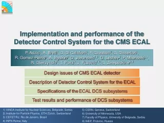
Implementation and performance of the Detector Control System for the CMS ECAL. P. Adzic 1 , A. Brett 2 , D. Di Calafiori 3 , F. Cavallari 4 , G. Dissertori 2 , R. Gomez-Reino 5 , A. Inyakin 6 , D. Jovanovic 7,1 , G. Leshev 2 , P. Milenovic 2,1 ,

E N D
Implementation and performance of the Detector Control System for the CMS ECAL P. Adzic1, A. Brett2, D. Di Calafiori3, F. Cavallari4, G. Dissertori2, R. Gomez-Reino5, A. Inyakin6, D. Jovanovic7,1, G. Leshev2, P. Milenovic2,1, R. Ofierzynski5, T. Punz2, J. Puzovic7,1, S. Zelepoukine8,2 Design issues of CMS ECAL detector Description of Detector Control System for the ECAL Specifications of theECAL DCS subsystems Test results and performance of DCS subsystems 1) VINCA Institute for Nuclear Sciences, Belgrade, Serbia 5) CERN, Geneva, Switzerland 2) Institute for Particle Physics, ETH Zürich, Switzerland 6) University of Minnesota, USA 3) CEFET/RJ, Rio de Janeiro, Brasil 7) Faculty of Physics, University of Belgrade, Serbia 4) INFN Rome, Italy 8) IHEP, Protvino, Russia
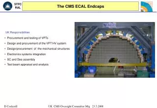
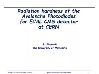
ECAL design criteria Physics goal - The discovery of the Higgs at the LHC Preferable channel for low mass Higgs search (mH<130 GeV):H→γγ Detector design criteria: • High energy and mass resolution • High degree of hermeticity and granularity • Compact,operated in magnetic field of 4T • Radiation toleranceto appropriate radiation doses • Neutron fluenceup to 5 ×1014 cm-2, integrated doseup to 50 kGy • Fast response time for 40 MHz bunch crossing rate. Crystals – PbWO4 Photo-detectors– APD and VPT Temperature sensitivity: -2.2% / OC Temperature sensitivity: -2.3% / OC
Temperature Stability Issue One of main ECAL design challenges: Stabilization of crystal volume temperature to 0.05 oC 0.45 A/channel 1 A/board Total heat power dissipated in the whole calorimeter ~300 kW Efficient removal of all excess heat is critical for the stable operation of the detector. Systems of crucial importance for the ECAL: Cooling system & Detector Control System Detector Control System
ECALDetector Control System Main design objectives and functionalities: • Monitoring of the crystal and APD temperature stability(18.00oC ± 0.05oC), as well as humidity level inside theECAL, • Monitoring of ECAL electronics environment temperature and water-leakage sensors, • Automatic ECAL protection in case of problematic situations (hardwired interlocks, predefined control actions etc.), • Software control of parameterization and functioning of ECAL sub-systems (HV, LV, Cooling, ESS, PTM/HM, Laser monitoring, DCUs etc.). Hardware (autonomous) subsystemsof the DCS: • System for Precise Temperature Monitoring (PTM) • System for Humidity Monitoring(HM) • ECAL Safety System (ESS)
ECAL DCS layout Hardware Protocols Applications ECAL Cooling pipes Simatic S7 Cooling equipment PLC Cooling app CAN bus LV hardware LV cabling ECAL detector LV project interlocks CAEN OPC HV cabling HV hardware HV project Sensors: Cabling Simatic S7 RS485 ESS readout PLC ESS project ESS CAN bus PTM/HM readout PTM/HM project PTM/HM DCU readout DCU project PC APD/VFE/LVR parameters Laser hardware Laser project PC CMS network (Ethernet) CMS databases and control consoles
Precision temperature and humidity monitoring Functionality: Monitoring of temperature and relative humidityinside the ECAL detector; Data visualization and recording to CMS Conditions DB. Abnormal situation processing (over-temperature, high humidity); warnings/alarms to ECAL Supervisor to shutdown LV/HV. Sensors(tested for radiation / magnetic field tolerance): 360 + 80 temperature probes (EB + EE); pre-calibrated by manufacturer; Relative precision better than 0.01oC. 144 + 32 RH probes (EB + EE);Precision 5 %RH in range [20 – 90 %RH]. Readout: Separated from ECAL DAQ (non-stop operation, incl. CMS shutdown). Based on ELMB moduledeveloped in ATLAS (16-bit ADC / 64 ch. MUX). No electronics inside CMS (accessible during CMS shutdowns).
PTM/HM layout Network access USC55 Counting room UXC55 (balcony) CMS ECAL Cur.src (PTM) or RH-transmitter (HM) PC / PVSS Galvanic isolation from ECAL 2x CANbus cables 2x 40 = 80 STP cables DC Power supplies ELMB 100m 80 m Data collection and processing Sensors Readout PTM: 440 HM: 176 24x ELMBs 512 PTM channels 192 HM channels
PTM – readout stability PTM readout stability monitoring (by measuring a 100K 0.6 ppm/oC reference resistor) H4 testbeam (August 2007) 2.0oC /div Ambient temperature (PTM rack) PTM readout stability is better than 0.001oC PTM resolution is ~ 0.0008oC 0.01oC /div Reference resistor as a sensor time period ~ 60 hours
PTM – readout chain noise Noise in the PTM readout chain CMS (August 2007) EB+14 / SM-15 Ambient temperature (PTM rack) time period ~11 hours 0.1oC /div Noise is negligible: at the level of resolution = ~ 0.001oC ~0.05oC oscillations are from Cooling system regulation feedback loop not yet finally adjusted SM-15 grid temperatures (cooling ON, LV ON) 0.01oC /div
ECAL Safety System (ESS) • Full autonomy of the system in every aspect and functionality; • Independent and reliable temperature monitoring of ECAL FEelectronics; Precision: 0.1oC • Detection of water leakage (WLD) inside the ECAL; • Reliable hardware interlocks and software signals to • 1. HV system crates (hardware interlock signals), • 2. LV system crates (hardware interlock and “power cut” signals), • 3. Cooling system (water flow and temp., PLC watchdog, WLD actions); • 4. operator and system experts (PVSS alerts, SMS and Email alerts etc.); • Radiation tolerance in accordance with CMS radiation dose specifications; • Maximum level of robustness, reliability and maintainability;
Implementation of the ESS • Three interconnected system layers: • ESS Front-End layer– signal conversion, channel multiplexing, • ESS PLC layer – data acquisition and processing, control signal generation, • external interfaces to other systems (LV, HV, Cooling etc.) • ESS software layer– monitoring and software control of the system.
FEcomponents of theESS • ESS Temperature sensors: • 288 + 64 SMD, 470 Ω NTC thermistors • positioned in redundant pairs • 8 per EB SM • 8 per EE quadrant • Calibrated to absolute precision of 0.2 oC. ESS Readout Unit: • Multiplexing + Resistant Bridge Front-end • Redundant temperature readout: 1 unit - 4 Super Modules, 12 units in total (ЕЕ+ЕB+ЕB+ЕЕ) • Reliability analysis ESS Water leakage detection: • Commercial sensor byRLE Technology • 2 wires with non-conductive coating • 2 wires with conductive polymer coating • Determines presence ofwater leakage
SubsystemS7–400H: Redundant information processing, Redundant communication with ESS software layer. SubsystemS7– 300: Redundant communication with S7-400Hpart of ESS PLC, Redundant RS485 communication with FE layer (via ESSprotocol); external signal inputs; Interlockand control signal outputs. ESS PLC system Based on industrial SiemensPLCSIMATICS7 controllers Fault-tolerantsystem for most of critical situations Fail-securesystem for all other situations • Digital filtering • Second order IIR NF filter (Butterworth) • Stable, tolerant to digitalization effects • andchoice of initial conditions
ESS performance One SEEeffect: σSEE= NSEE/ФEKV = 5.6 х 10-12cm2 SEE Results of exposition of ESS electronics to proton irradiation (up to 60 Gy) Results of exposition of ESS sensors to proton irradiation (up to 200 kGy) Negligible cross section forSEE! Temp. difference for redundant sensors Temperature fluctuations (noise) for SM 26 ~0.08°C ~0.015°C
Monitoring and control software CMS DCS PTM ESS HM LV HV Cooling
ECAL DCS in ECAL test setups ECAL DCS supports ECAL test setups for several years growing itself from prototypes towards the final full scale version. • ECAL DCS • simultaneously supported • up to 4 ECAL setups • running at different locations: • ECAL electronics • integration center • H4/H2 testbeams and • cosmic calibrations • CMS MTCC 2006 • ECAL barrel SM tests • during insertion in CMS • now supports 1x SM • for CMS “global runs” DCS availabilty = 99.9% (1% NICE patches, power cuts)
Summary and outlook Design and implementation process was not easy and straightforward but ECAL DCS now provides: Well tested and proven safety functionality (ESS); High precision measurements for temperature monitoring (PTM); Integrated controls/monitoring for all ECAL services (all other DCS subsystems). Installation/commissioning status: ECAL services and ESS hardware mostly pre-tested and installed; PTM/HM hardware under test/calibration in the lab – to be moved to P5 soon. Subsystem specific commissioning is ongoing (where standalone tests possible). DCS overall system commissioning to be started immediately after the ECAL cabling (now in progress) is done. Thereafter ECAL DCS will enter routine operation phase – for next ~10 yrs.
SUPERCONDUCTING COIL MUON ENDCAPS Silicon Microstrips MUON BARREL Pixels Cathode Strip Chambers (CSC) Drift Tube Resistive Plate Resistive Plate Chambers (RPC) Chambers (RPC) Chambers (DT) Compact Muon Solenoid CALORIMETERS HCAL ECAL Scintilating PbWO4 crystals Plastic scintillator/brass sandwich IRON YOKE TRACKER
Physics goal - The discovery of the Higgs at the LHC Preferable channel for low mass Higgs search (mH<130 GeV):H→γγ Detector design criteria: High energy and mass resolution: Stochastic term (a): 2.7% (5.7%)(photo and lateral fluctuations), Noise (b): 155(205)MeV(electronics, APD leak currents), Constant term (c): 0.55% (non-uniformities, leakages, calibration) High degree of hermeticity and granularity Compact,operated in magnetic field of 4T Radiation toleranceto appropriate radiation doses: Neutron fluence 1.2 ×1013 cm-2, integrated dose 1 kGy at positionh = 0 Neutron fluence5 ×1014 cm-2, integrated dose50 kGyat positionh = 2.6. Fast response time for 40 MHz bunch crossing rate. ECAL design criteria
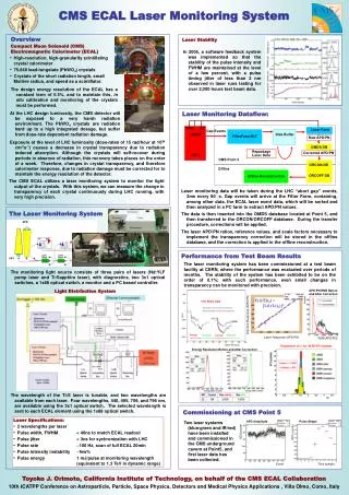
Stabilization of ECAL parameters • Laser system for control of • crystal transparency • Two wavelenghts • (440 nm, 495 nm) • Pulse energy 1 mJ • (1.3 TeVin dynamic range) • Temperature stabilization • Stabilized water temperature at • 18.00 ± 0.05 °C; • Thermal shielding of ECAL crystals • from TrackerandECAL electronics; • Water cooling of ECAL electronics. • Stabilized HV power supply • for APD diodes • C.A.E.N. SY1527 (0-500V, 15mA) • Output voltage stability ~350 ± 0.02 V
ECAL Cooling, LV, HV -- overview ECAL cooling system primary circuit – CMS chilled water plant (11-14oC). secondary circuit – ECAL cooling (actually a heater) to get 18oC. distribution infrastructure – individual pipes to each Supermodule/Dee. flow-meters / temperature sensors / valves – on each pipe. PLC based monitoring / regulation / controls – monitored with DCS application. ECAL LV system 5V DC regulated to all ECAL on-detector electronics. 136 crates (Wiener MARATON), 850 channels in total. distribution infrastructure – individual cables to SMs/Dees. remote controls of Wiener crates via CAN bus – DCS application. ECAL HV system 400 V DC regulated to APDs/VPTs. 18 crates (CAEN sy1527), 1224 channels in total. distribution infrastructure – individual cables to SMs/Dees. remote controls of CAEN crates via Ethernet – DCS application.
ECAL DCU readout, Laser -- overview ECAL DCU readout provides monitoring of detector and on-detector electronics parameters: crystal/APD temperatures APD leakage currents LV supply values on LVR VFE/FE card temperatures ~100,000 values for the whole ECAL Readout via DAQ – DCS application takes data from XDAQ application. ECAL Laser monitoring provides a reference light signal to every crystal in order to calibrate on-detector electronics. A dedicated laser control system indicates its state and the main laser parameters (just a few values) to a DCS application.
ECAL DCS interconnections ECAL DCS receives commands: 1. from CMS “Run Control” via CMS DCS (CMS operational mode) or 2. from ECAL “Run Control” (ECAL local operational mode, commissioning)
PTM/HM readout system – ELMB ELBM boards developed by ATLAS DCS in collaboration with NIKHEF • Main features: • Master/Slave Processors: • ATMEL AVR RISC (ATmega103) • • CAN Controller (Infineon) • (CAN Baud rate and Node ID • setting via DIP switch) • • 2 High Density SMD Connectors • • 64 analogue input channels • Optional 64 ch. 16+7 bit ADC I/O Lines Available: • 6 external interrupt inputs • 4 bi-directional I/O ports (A, D, E, F) for ext. SRAM (A), analog inputs (F) • 1 bi-directional I/O port (B) used for jumper reading. • 8 bit Digital Output port (C)
Implementation of the PTM system PTM temperature sensors: In total 360 + 80 100 kOhms NTC thermistors (Bethaterm) positioned at 8 measurement points inside SM and 2 points at cooling pipes Signal conversion and channel multiplexing Data acquisition, monitoring
Implementation of the HM system HM humidity sensors: In total 144 + 32 UPS600 sensors by Ohmic Instruments positioned at 4 measurement points inside SM Signal conversion and channel multiplexing Data acquisition, monitoring
PTM performance H4 testbeam (August 2007) CMS (August 2007): EB SM-15 2.0oC /div 0.1oC /div Ambient temperature (PTM rack) Ambient temperature (PTM rack) time period ~ 60 hours time period ~11 hours Reference resistor as a sensor 0.01oC /div PTM readout stability monitoring (by measuring a 100K 0.6 ppm/oC reference resistor) Stability is better than 0.001oC Resolution is ~ 0.0008oC SM-15 grid temperatures (cooling ON, LV ON) 0.01oC /div Noise is negligible – at the level of resolution (~0.05oC oscillations are from the cooling system regulation feedback loop not yet finally adjusted)
FEcomponents of theESS ESS temperature sensors: In total 288 + 64 SMD, 470 Ohms NTC thermistors (EPCOS) positioned in pairsat each measurement point ( “twin” sensors). • 8 / EB SM • 8 / EE quadrant • Sensor calibration withrelative precision better then 0.2 oC. Special procedure developed. Delivered toCERN inJanuary 2006: Produced by: CMS Belgrade Group:
FEcomponents of theESS Multiplexer Max4582: • CMOS compatabile • Temperature range 0°C - 70°C • ON-resistance • до 150 Ohms на 5V • OFF-leakage current 1nA at 25°C • Low level of channel crosstalk • tested for tolerance to • certain rad. doses Resistant Bridge Front End (RBFE) NTC 470 Ohms • Resistant Bridge Front-End block of electronics: • Bidirectional programableinternal current source (500mA), • Differential amplifier, optimal amplification adjustment for ESS, output range: 0 - 4V, • Analog switches, 8 masurement modes, digitally controlled by three bits (Ck0, Ck1 и Ck2), • Removes voltage offsets, thermocouple effects, dependence on supply voltages and temperature drifts
FEcomponents of theESS ESS Readout Unit: • Multiplexing + Resistant Bridge Front-end • Redundant temperature readout: 1 unit - 4 Super Modules, 12 units in total (ЕЕ+ЕB+ЕB+ЕЕ) • Reliability analysis Water leakage detection (WLD) inside the ECAL: • Commercial sensor-cable byRLE Technology • 2 wires with non-conductive coating • 2 wires with conductive polymer coating • Determines both presence and position of water leakage in the system
ESS digital filtering Basic filter design objectives: • Fast filter response to impulse and step excitation (about 5 – 6 samples to reach90% of final response value); • Small “overshot” valuefor impulse and step response (about 10 – 15 % of impulse/step amplitude); • Low filter order (small number of filter coefficients) • NF filter Frequency selectivity not of primary importance. (cut frequency of PB ~ 5–10 Hz, signal attenuation in NB ~ 60 dB) • Stability. Tolerant to digitalization effects andselection of initial conditions. Results: Digital IIR filter of second order (based on Butterworth function) withresponse function: Stable, tolerant to digitalization effects andselection of initial conditions!!!
ESS irradiation tests Radiation effects: • Cumulative radiation effects(ionization effects, displacement effects) • „Instantaneous” radiation effects(energy deposition of one passing particle) Irradiation performed with OPTISproton 64 MeV beam atPSI: • Maximal flux 1.1 х 1010protons cm-2 s-1 (minimal flux 1.1 х 107protons cm-2 s-1) Irradiation tests of: • ESS sensors and cables for sensor readout (up to 200kGy) • Maxim 4582multiplexers, RBFEelectronics andPICmicrocontrollers (up to 60 Gy). Test-boardwith irradiated sensors and ESS FE electronic components Results of exposition of sensors to “maximal” flux irradiation (8 hours) No change of any analogous parameter. One SEEeffect:σSEE= NSEE/ФEKV = 5.6 х 10-12cm2 Negligible cross section forSEE! SEE
Position 1 mm Resolution(mm) Energy (GeV) ECAL Test-beam results with final electronics Energy Resolution(%) Energy (GeV) 0.6% at 50 GeV. 0.85 mm at 50 GeV. Target calorimetry resolution achieved with new electronics design!
ECAL Test-beam results with final electronics We cannot calibrate every crystal with an electron beam. Obtain a first calibration point from component data: crystal light yield, APD & PA gain. Labo LY corr s = 4.05% Test Beam LY Test Beam LY – Labo LY corr Relative channel calibration can be obtained from Lab with a precision of 4 % In situ: Fast intercalibration based on f symmetry in energy flow 2% in few hours Energy/momentum of isolated electron from W→ en 0.5% in 2 months Absolute energy scale from Z → e+e-
Conclusions and outlook • Stabilization and control of ECAL working parameters to high precissionnecessary in order to achieve required detector performance; • Detector Control System (DCS) is of crucial importance; • Applied characteristic hardware solutions: • RBFE block, redundant configuration; • Applied characteristic software solutions : • FSMconcept, ESSprotocol, digital filtering; • Tested and proved radiation toleranceof all PTM/HM and ESS system components to appropriate radiation doses; • DCS performancein accordance with design criteria; • Commissioning and integration of the DCSin CMS caverns in final phase; • Looking forward to testing all ECAL DCS systems on the full scale for the first time in October this year