Download
1 / 12
120 likes | 236 Views
The Control System for the ATLAS Pixel Detector. Kerstin Lantzsch, CERN/Bergische Universität Wuppertal Gentner Day, 18.11.2009. The ATLAS Pixel Detector. evaporative Cooling System 88 Parallel Cooling Circuits/loops : 56 PCCs with 2 staves each 24 PCCs with 2 disk sectors each

E N D
The Control System for the ATLAS Pixel Detector Kerstin Lantzsch, CERN/Bergische Universität Wuppertal Gentner Day, 18.11.2009
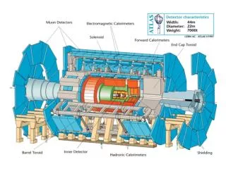
The ATLAS Pixel Detector evaporative Cooling System 88 Parallel Cooling Circuits/loops: 56 PCCs with 2 staves each 24 PCCs with 2 disk sectors each 8 PCCs for 272 optoboards • 1744 detector modules • 3 Barrel Layers • 3 Disks per Endcap • 272 Halfstaves/Disksectors • optical data transfer: • 272 readout groups (Halfstaves/Disksectors) • 80 million readout channels length: 1.3 m, 34.4 cm, weight: ~4.4 kg Kerstin Lantzsch, Gentner Day 18.11.2009
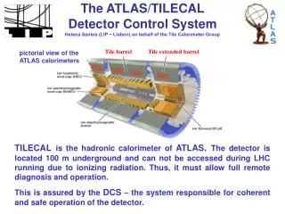
Tasks of the Detector Control System • ControlIntegration of the Hardware into the DCS software and its control for the supply of the detector. • Monitoring and ArchivingSupervising values which are relevant to the state of the detector, and archive them for later trouble shooting. • OperationProvide the tools for the operation of the detector by the shift crew. • InterlockEnsure the safety of the detector and personnel. Kerstin Lantzsch, Gentner Day 18.11.2009
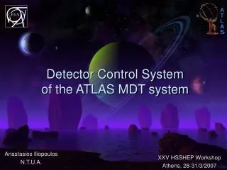
Hardware The DCS hardware supervises detector modules, the optoboards, the readout crates, and the environment. It consists of: • The power supply system • Monitoring units • The interlock system Kerstin Lantzsch, Gentner Day 18.11.2009
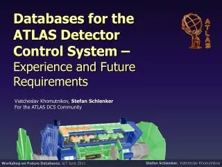
Software PVSS II (by ETM, Eisenstadt, Austria) was selected by the LHC experiments' Joint Controls Project (JCOP) as a base for the individual control systems. Pixel DCS is built of 3 software layers: • Frontend Integration Tools (FIT): • Establish communication to the hardware • Data structures follow hardware properties • System Integration Tool (SIT): • Mapping between hardware and detector • Initialises archiving of DCS data • Finite State Machine (FSM): • Overview and Operation of detector. Main shifter tool. • Protection routines • Tools are provided by JCOP framework and ATLAS DCS Kerstin Lantzsch, Gentner Day 18.11.2009
The FSM • „The FSM“ is a hierarchical structure of objects that behave like separate FSMs, they are described by states, transitions, and commands. • In the hierarchy, commands are propagated down to the children, states are propagated up. • A tool for creation of control systems on FSM basis is provided centrally: SMI++ (State Management Interface). • The FSM is a combination from smi++ and PVSS. While state and command propation are handled by smi processes, the generation of the device states and the execution of commands is pure PVSS. • While there are some central requirements, the items specific for subdetector operation must be implemented by the subdetectors. • ATLAS specific is the subdivision into state (operational mode) and status (health of the system) Kerstin Lantzsch, Gentner Day 18.11.2009
The Pixel FSM • The FSM tree for the Pixel detector is driven by its mechanical structure, and granularity of readout and services, while the states and commands are adapted for operational aspects specific to the pixel detector. This is driven by the readout group and its devices. • Additional layers of protection are in the form of software interlocks built into the FSM scripts, and perform automated actions to protect the detector, which can not be expected of the shifter. Kerstin Lantzsch, Gentner Day 18.11.2009
The Pixel FSM Tree Subdetector DAQ-Partition Layer Cooling Readout / services Device Units Kerstin Lantzsch, Gentner Day 18.11.2009
The Readout Group • The Readout group mainly consists of the 6/7 Detector Modules serviced by one Optoboard, as well as their common supply units. • The synchronization of commands is handled by a special Device Unit. • The Device Units are rather complex (e.g. Module state and status is depending on 6 parameters). The calculation of state and status is distributed over 17 processes („managers“) on 3 DCS-PCs. These PVSS-based scripts are also responsible for software Interlocks in case of • high temperature, • critical current values, • problems in the cooling system. Kerstin Lantzsch, Gentner Day 18.11.2009
State Diagram of the Readout Group • The State of the readout group is determined by the state of the device units • Not all states can be reached by DCS actions. Most prominently READY can only be reached passively, after the DAQ sends the configuration to the modules. • Defined States allow for the independent operation of single components. The pixel specific states are well-proven to be adequate for operation. Kerstin Lantzsch, Gentner Day 18.11.2009
Detector Overview • Overview over all the Readout groups in one panel • Not all nodes must contribute to the parent‘s state (e.g. disabled due to hardware problems) • In STANDBY for „Beam“ Kerstin Lantzsch, Gentner Day 18.11.2009
Summary and outlook • Work on the FSM had to cover the evolving requirements from moving from the 10% system test, to the final system in the pit which is the main interface for the operation of the detector. • In addition to providing software interlock, scripts are in place which handle the reaction to and interaction with external systems, mainly the cooling system, but also handling of beam related issues. • The handling of the DCS crates is integrated into the FSM, allowing for easier recovery in case of shutdowns. • Besides the work on the detector control system, I want to start looking into correlations between information from Pixel and the ATLAS Beam Conditions Monitor (BCM). Kerstin Lantzsch, Gentner Day 18.11.2009