Download
1 / 36
360 likes | 372 Views
Transmission Machine Components. Gears. Gears simply change the parameters of mechanical power. Pitch-Line Velocity. P. r 1. r 2. gear. pinion. Tooth Forces. T 2. F 2. r 2. T 1. r 1. F 1. Normal velocity must match. Using similar triangles. v 2 cosθ 2 = v 1 cosθ 1

E N D
Gears • Gears simply change the parameters of mechanical power Pitch-Line Velocity P r1 r2 gear pinion
Tooth Forces T2 F2 r2 T1 r1 F1
Normal velocity must match. Using similar triangles v2 cosθ2 = v1 cosθ1 where v1 = ω1 . O1C ; v2 = ω2 . O2C Want constant rotation rate ratio ω2 /ω1 = v2 . O1C/v1 . O2C = O1C.cosθ1 /O2C.cosθ2 = O1 C1 /O2 C2 = O1 P / O2 P Point P must be fixed
Effect of Errors Shafts at spec. distance Shafts farther apart than spec.
Involute Tooth Profile • The two curved surfaces of mating teeth, contact as a line
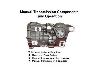
Types of Gears • Spur Gears • Teeth are parallel to rotation axis • Transmit power between shafts with parallel axes • Helical Gears • Teeth inclined to the axis of rotation • Used for the same applications as spur gears, but have less noise due to gradual tooth engagement
Types of Gears, cont. • Bevel Gears • Teeth on a conical Surface • Used with intersecting shafts • Worm Gears • Similar to a screw • Used with non-parallel and non-intersecting shafts typically with high speed ratios
Rack and Pinion • A rack is an unwound spur gear • Turns rotary motion in to linear motion
Anatomy of a Gear • Pitch Circle • Theoretical circle upon with all calculations are based • Diametral Pitch • Module • Pressure Angle • For gears to work together they must have the same pitch (or module) and pressure angle
Multiple Gear Stages • Gear ratios from a multi-stage gear train multiply together T3 T2 T4 T1 2:1 reduction 2:1 reduction 2:1 reduction Overall a 8:1 reduction
Efficiency • In reality gears are not 100% efficient • Good quality spur gears are typically in the 90+ % efficiency range • This can be a problem with multiple (large) gear reductions Each a 2:1 reduction with 95% efficiency Overall a 32:1 reduction, but only 77% efficient
Belts are essentially the same as spur gears but they have the ability to have large offsets Belts and Chains P1 P2
Slip • Belts rely on friction and to prevent slip tension must be maintained • Chains and timing belts that have teeth with positive engagement can help prevent slip
Shafts Energy used to overcome the forces resulting from misalignment will reduce the overall efficiency of your system Parallel misalignment Angular misalignment This is the key to doing well in the transmission contest
Pins • Pins hold two parts together based upon the shear strength of the pin • Pins are good when the joint must take both thrust and shear • Pinned joints are easy to analyze and reliable • Pinned joints can be used as a mechanical fuse • Pinned joints are difficult to assemble and disassemble because pins are typically press fit into place shaft gear pin
Keys • Keys transmit torque in shear across the length of the key • Keys have all the advantages of pins, but they are easy to install in remove • Keys do not take any axial load Woodruff key Used to reduce stress concentrations in the shaft
Clamp Fit • Clamps depend upon friction and the bolted connection between two parts (or a single part with a flexure) to develop the clamping force • Clamped connections can be easy and reliable for low torque applications
Press (Interference) Fits • Two parts can be pressed together if the hole is manufactured smaller than the shaft that is installed • The load between these two parts is taken in friction developed by the strain of the press fit • Manufacturing tolerances are very tight for this type of connection • For a 0.25” diameter shaft with a class FN2 fit • Shaft 0.2510” – 0.2514” • Hole 0.2500” – 0.2506” • Difficult to disassemble without damage to the parts
Splines • Splines are essentially matching internal and external gears used to transmit torque • Splines are extremely reliable and efficient • Splines are difficult to manufacture
Retaining Rings • Retaining rings are used to constrain things axially in one direction on a shaft • Installed by machining a groove into one of the mating parts • Can be made external or internal External E-Style External Internal
Shaft Connections Coupler transmits torque and allows for misalignment Key or set screw transmits torque
Couplers • Bellows • Spider Coupling • Helical • Universal Joint
Bushings have sliding contact and rely on low friction at the point or line of contact Bushings r F
Rolling Element Bearings • Replace sliding contact with rolling contact which is much more efficient Outer Race Ball Separator (retainer) Inner Race Image courtesy of Barden Precision Bearing
Rolling Contact ωb rb V ω1 ri ro rLi rLo
Spherical Bearings • Allows for misalignment in all rotational degrees of freedom • Constrains in all translational degrees of freedom • Good for low speed / high load applications
Electric Motors • Torque is proportional to current • Speed is proportional to voltage • An electric motor generates an Electromotive Force (back EMF) as it spins • A portion of the input voltage goes to doing work and a portion goes to overcome the back EMF
Kt Ke
Electric Motors For a given voltage
Electric Motor Power Can’t always operate here due to heat