Download
1 / 43
430 likes | 612 Views
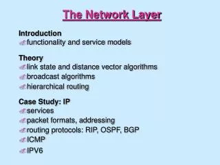
Computer Networks The Network Layer . Lecture 7. Adrian Sergiu DARABANT. The Network Layer. The Internet Protocol -IP. The Internet (IP) Protocol IPv4 addressing Moving a datagram from source to destination Datagram format IP fragmentation ICMP: Internet Control Message Protocol

E N D
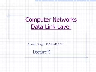
Computer NetworksThe Network Layer Lecture 7 Adrian Sergiu DARABANT
The Internet Protocol -IP The Internet (IP) Protocol • IPv4 addressing • Moving a datagram from source to destination • Datagram format • IP fragmentation • ICMP: Internet Control Message Protocol • DHCP: Dynamic Host Configuration Protocol • NAT: Network Address Translation • Routing
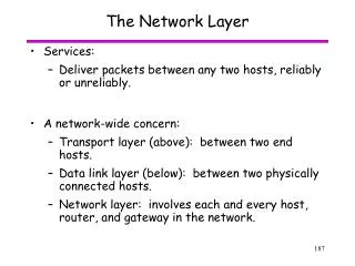
ICMP protocol • error reporting • router “signaling” • IP protocol • addressing conventions • datagram format • packet handling conventions • Routing protocols • path selection • RIP, OSPF, BGP forwarding table The Internet Network Layer Transport layer: TCP, UDP Network layer Link layer physical layer
223.1.1.2 223.1.2.1 223.1.3.27 223.1.3.1 223.1.3.2 223.1.2.2 IP Addressing 223.1.1.1 • IP address: 32-bit identifier for host, router interface • interface: connection between host/router and physical link • router’s typically have multiple interfaces • host may have multiple interfaces • IP addresses associated with each interface 223.1.2.9 223.1.1.4 223.1.1.3 223.1.1.1 = 11011111 00000001 00000001 00000001 223 1 1 1
IP Addressing 223.1.1.1 • IP address: • network part (high order bits) • host part (low order bits) • What’s a network ?(from IP address perspective) • device interfaces with same network part of IP address • can physically reach each other without intervening router 223.1.2.1 223.1.1.2 223.1.2.9 223.1.1.4 223.1.2.2 223.1.1.3 223.1.3.27 LAN 223.1.3.2 223.1.3.1 network consisting of 3 IP networks (for IP addresses starting with 223, first 24 bits are network address)
IP Addressing 223.1.1.2 223.1.1.1 223.1.1.4 How to find the networks? • Detach each interface from router, host • create “islands of isolated networks 223.1.1.3 223.1.7.0 223.1.9.2 223.1.9.1 223.1.7.1 223.1.8.1 223.1.8.0 223.1.2.6 223.1.3.27 Interconnected system consisting of six networks 223.1.2.1 223.1.2.2 223.1.3.1 223.1.3.2
multicast address 1110 network host 110 network 10 host IP Addresses given the notion of “network”, let’s re-examine IP addresses: “class-full” addressing: class 1.0.0.0 to 127.255.255.255 A network 0 host 128.0.0.0 to 191.255.255.255 B 192.0.0.0 to 223.255.255.255 C 224.0.0.0 to 239.255.255.255 D 32 bits
IP Addressing: CIDR • Classful addressing: • inefficient use of address space, address space exhaustion • e.g., class B net allocates enough addresses for 65K hosts, even if we only have 2K hosts in that network • CIDR:Classless InterDomain Routing • network portion of address of arbitrary length • address format: a.b.c.d/x, where x is # bits in network portion of address host part network part 11001000 00010111 00010000 00000000 200.23.16.0/23
IP Subnet • Basic concept: • A subset of a class A, B or C network. • IP addresses that do not use subnets consists of • A network portion, and • A host portion. • Represents a static two-level hierarchical addressing model.
IP Subnet (cont) • IP subnets introduces a third level of hierarchy. • A network portion • A subnet portion • A host portion • Allow more efficient (and structured) utilization of the addresses. • Uses network masks. usually handled together as network but with substructure
CIDR – Introduction • The size of the global routing tables have grown very fast in recent years. • Caused routers to become saturated. • CIDR is a new concept to manage IP networks. • Classless Inter Domain Routing. • No concept of class A, B, C networks. • Reduces sizes of routing tables.
CIDR - Basic Idea • An IP address is represented by a prefix, which is the IP address of the network. • It is followed by a slash, followed by a number M. • M: number of leftmost contiguous bits to be used for the network mask. • Example: 144.16.192.57 / 18
CIDR - Rules • The number of addresses in each block must be a power of 2. • The beginning address in each block must be divisible by the number of addresses in the block. • A block that contains 16 addresses cannot have beginning address as 193.226.40.36. • But the address 193.226.40.64 is possible !
IP/Netmask - examples 209.220.186.8 209.220.186.9 209.220.186.10 209.220.186.11 209.220.186.8/255.255.255.252=> 209.220.186.8/255.255.255.248=> 209.220.186.8 209.220.186.9 209.220.186.10 209.220.186.11 209.220.186.12 209.220.186.13 209.220.186.14 209.220.186.15 Invalid combination 209.220.186.8/255.255.255.240
Network masks • Network mask 255.0.0.0 is applied to a class A network 10.0.0.0; • Mask = series of contiguous 1’s followed by a series of contiguous 0’s 11111111 00000000 00000000 00000000 NETWORK HOST
Natural Masks • Provide a mechanism to split the IP address 10.0.0.20 into: • A network portion – 10; • A host portion – 20; IP Address: 10.0.0.20 00001010 00000000 00000000 00010100 Mask: 255.0.0.0 11111111 00000000 00000000 00000000 Network Host
Natural masks • Class A, B and C addresses • Have fixed division of network and host portions • Can be expressed as masks • Natural Masks • Class A: 255.0.0.0 • Class B: 255.255.0.0 • Class C: 255.255.255.0
Subnets out of masks • Masks are very flexible. • Using masks, networks can be divided into smaller subnets. • How? • By extending the network portion of the address into the host portion. • Advantage gained: • We can create a large number of subnets from one network. • Can have less number of hosts per network.
Network Address Network Mask 255.255.255.0 IP Address 193.226.40.45 Network Address 193.226.40.0 AND Network Mask 255.255.255.224 IP Address 193.226.40.45 Network Address 193.226.40.32 Network Address ? AND
Subnetting • Basic concept • The same network can be configured with different masks. • Can have subnets of different sizes. • Allows better utilization of available addresses.
Example • Suppose we are assigned a Class C network 193.226.40.0 • To be divided into three subnets. • Corresponding to three departments. • With 110, 45 and 50 hosts respectively D1 110 D2 45 D3 50
Example (cont) - Options Network too small • Rules: • First IP address = Network Address • Last IP address = Broadcast Address
How does one get IP Addresses ? Q: How does a network get the network part of IP addr? A: it gets allocated from the portion of its provider ISP’s address space ISP's block 11001000 00010111 00010000 00000000 200.23.16.0/20 Organization 0 11001000 00010111 00010000 00000000 200.23.16.0/23 Organization 1 11001000 00010111 00010010 00000000 200.23.18.0/23 Organization 2 11001000 00010111 00010100 00000000 200.23.20.0/23 ... ….. …. …. Organization 7 11001000 00010111 00011110 00000000 200.23.30.0/23
Private Addreses Not routed in Internet Why ?
Routing tables (static) The route command – (Windows/Linux/other OS)
E B A source IP addr misc fields dest IP addr data 223.1.1.1 223.1.2.1 223.1.1.2 223.1.2.9 223.1.1.4 223.1.2.2 223.1.1.3 223.1.3.27 223.1.3.2 223.1.3.1 Datagram: from source to destination forwarding table in A IP datagram: datagram remains unchanged, as it travels source to destination Addresses are fields of interest here
B A E 223.1.1.1 223.1.2.1 223.1.1.2 223.1.2.9 223.1.1.4 223.1.2.2 223.1.1.3 223.1.3.27 223.1.3.2 223.1.3.1 Datagram: from source to destination forwarding table in A misc fields data 223.1.1.1 223.1.1.3 Starting at A, send IP datagram addressed to B: • look up net. address of B in forwarding table • find B is on same net. as A • link layer will send datagram directly to B inside link-layer frame • B and A are directly connected
B A E 223.1.1.1 223.1.2.1 223.1.1.2 223.1.2.9 223.1.1.4 223.1.2.2 223.1.1.3 223.1.3.27 223.1.3.2 223.1.3.1 Datagram: from source to destination forwarding table in A misc fields data 223.1.1.1 223.1.2.3 Starting at A, dest. E: • look up network address of E in forwarding table • E on different network • A, E not directly attached • routing table: next hop router to E is 223.1.1.4 • link layer sends datagram to router 223.1.1.4 inside link-layer frame • datagram arrives at 223.1.1.4 • continued…..
B A E 223.1.1.1 223.1.2.1 223.1.1.2 223.1.2.9 223.1.1.4 223.1.2.2 223.1.1.3 223.1.3.27 223.1.3.2 223.1.3.1 Datagram: from source to destination forwarding table in router misc fields data 223.1.1.1 223.1.2.3 Arriving at 223.1.4, destined for 223.1.2.2 • look up network address of E in router’s forwarding table • E on same network as router’s interface 223.1.2.9 • router, E directly attached • link layer sends datagram to 223.1.2.2 inside link-layer frame via interface 223.1.2.9 • datagram arrives at 223.1.2.2!!!(hooray!)
IP Datagram IP protocol version number 32 bits total datagram length (bytes) header length (bytes) type of Service(8) head. Len(4) Ver(4) Length(16) for fragmentation/ reassembly 13 bit fragment offset(13) “type” of data Flgs(3) 16-bit identifier(16) max number remaining hops (decremented at each router) upper layer Prot(8) time to Live(8) Header Internet checksum(16) DF+MF 32 bit source IP address(32) 32 bit destination IP address(32) upper layer protocol to deliver payload to E.g. timestamp, record route taken, specify list of routers to visit. Options (if any) how much overhead with TCP? 20 bytes of TCP 20 bytes of IP = 40 bytes + app layer overhead data (variable length, typically a TCP or UDP segment)
Fragmentation/Reassembly • network links have MTU (max.transfer size) - largest possible link-level frame. • different link types, different MTUs • large IP datagram divided (“fragmented”) within net • one datagram becomes several datagrams • “reassembled” only at final destination • IP header bits used to identify, order related fragments fragmentation: in: one large datagram out: 3 smaller datagrams reassembly
length =1500 length =1500 length =4000 length =1040 ID =x ID =x ID =x ID =x fragflag =0 fragflag =1 fragflag =0 fragflag =1 offset =0 offset =0 offset =1480 offset =2960 One large datagram becomes several smaller datagrams Fragmentation/Reassembly Example 4000 byte datagram MTU = 1500 bytes
NAT – Network Address Translation rest of Internet local network (e.g., home network) 10.0.0/24 10.0.0.1 10.0.0.4 10.0.0.2 138.76.29.7 10.0.0.3 Datagrams with source or destination in this network have 10.0.0/24 address for source, destination (as usual) All datagrams leaving local network have same single source NAT IP address: 138.76.29.7, different source port numbers
NAT – Network Address Translation • Motivation: local network uses just one IP address as far as outside word is concerned: • no need to be allocated range of addresses from ISP: - just one IP address is used for all devices • can change addresses of devices in local network without notifying outside world • can change ISP without changing addresses of devices in local network • devices inside local net not explicitly addressable, visible by outside world (a security plus).
3 2 1 4 S: 10.0.0.1, 3345 D: 128.119.40.186, 80 S: 138.76.29.7, 5001 D: 128.119.40.186, 80 1: host 10.0.0.1 sends datagram to 128.119.40.186, 80 S: 128.119.40.186, 80 D: 10.0.0.1, 3345 S: 128.119.40.186, 80 D: 138.76.29.7, 5001 NAT – Network Address Translation NAT translation table WAN side addr LAN side addr 138.76.29.7, 5001 10.0.0.1, 3345 …… …… 10.0.0.1 10.0.0.4 10.0.0.2 138.76.29.7 10.0.0.3 4: NAT router changes datagram dest addr from 138.76.29.7, 5001 to 10.0.0.1, 3345 3: Reply arrives dest. address: 138.76.29.7, 5001
NAT – Network Address Translation • 16-bit port-number field: • 60,000 simultaneous connections with a single LAN-side address! • NAT is controversial: • routers should only process up to layer 3 • violates end-to-end argument • NAT possibility must be taken into account by app designers, e.g., P2P applications • address shortage should instead be solved by IPv6
UDP Checksum – for the entire datagram (header + data) Length >=8 – entire datagram
ICMP • Used by hosts, routers, gateways to communication network-level information • error reporting: unreachable host, network, port, protocol • echo request/reply (used by ping) • Network-layer “above” IP: • ICMP msgs carried in IP datagrams • ICMP message: type, code plus first 8 bytes of IP datagram causing error
ICMP TypeCodedescription 0 0 echo reply (ping) 3 0 dest. network unreachable 3 1 dest host unreachable 3 2 dest protocol unreachable 3 3 dest port unreachable 3 6 dest network unknown 3 7 dest host unknown TypeCodedescription 4 0 source quench (congestion control - not used) 8 0 echo request (ping) 9 0 route advertisement 10 0 router discovery 11 0 TTL expired 12 0 bad IP header