Download
1 / 27
280 likes | 377 Views
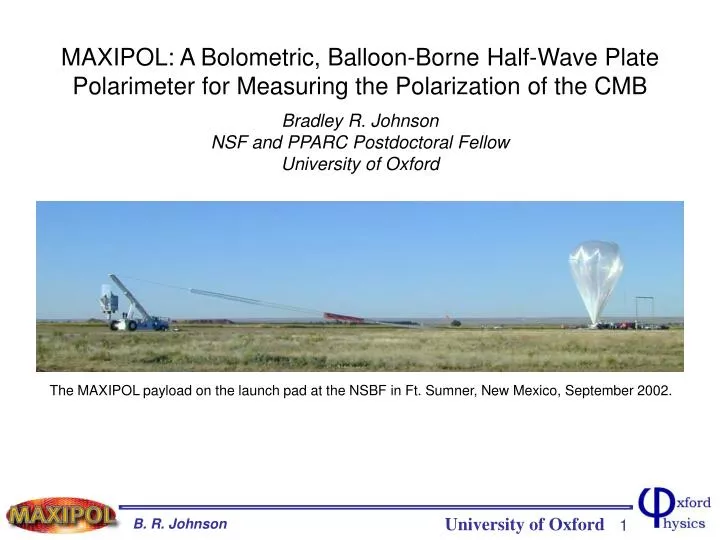
Title Slide. MAXIPOL: A Bolometric, Balloon-Borne Half-Wave Plate Polarimeter for Measuring the Polarization of the CMB Bradley R. Johnson NSF and PPARC Postdoctoral Fellow University of Oxford. The MAXIPOL payload on the launch pad at the NSBF in Ft. Sumner, New Mexico, September 2002.

E N D
Title Slide MAXIPOL: A Bolometric, Balloon-Borne Half-Wave Plate Polarimeter for Measuring the Polarization of the CMB Bradley R. Johnson NSF and PPARC Postdoctoral Fellow University of Oxford The MAXIPOL payload on the launch pad at the NSBF in Ft. Sumner, New Mexico, September 2002.
MAXIPOL Collaboration Matthew Abroe1 Peter Ade3 Jamie Bock4 Julian Borrill5,6 Jeff Collins2 Pedro Ferreira7 Shaul Hanany1 Andrew Jaffe8Bradley Johnson7 Terry Jones1 Adrian Lee2,9 Tomotake Matsumura1Paul Oxley1Bahman Rabii2 Tom Renbarger1 Paul Richards2 George Smoot2,6,9 Radek Stompor5 Huan Tran2 Celeste Winant2 Proty Wu10 Joe Zuntz8 1) School of Physics and Astronomy, University of Minnesota, Minneapolis, MN, USA 2) Department of Physics, University of California, Berkeley, CA, USA 3) Department of Physics and Astronomy, Cardiff University, Cardiff, UK 4) Jet Propulsion Laboratory, Pasadena, CA, USA 5) Computational Research Division, Lawrence Berkeley National Lab, Berkeley, CA, USA 6) Space Sciences Laboratory, University of California, Berkeley, CA, USA 7) Astrophysics, University of Oxford, Oxford, UK 8) Astrophysics Group, Blackett Lab, Imperial College, London, UK 9) Physics Division, Lawrence Berkeley National Lab, Berkeley, CA, USA 10) Department of Physics, National Taiwan University, Taipei, Taiwan
What are the Science Goals of MAXIPOL? 1) Implement half-wave plate (HWP) polarimetry in a CMB experiment. - MAXIPOL is a pathfinder experiment -- HWP polarimeter techniques and data analysis algorithms will be useful for B-mode experiments. - MAXIPOL is a reimplementation of the MAXIMA hardware - MAXIMA reported best receiver NET -- 40 K sec. - We wanted to develop a polarization modulator -- HWP polarimeter is the best. Attempt detection of E-mode signal. - Even with the high receiver sensitivity, predictions showed unambiguous E-mode detection would be challenging -- long integration time was required. - We collected data and data analysis is now concluding.
MAXIPOL Instrument • Flight proven • MAXIMA hardware. • Sun shields not • illustrated.
Half-Wave Plate (HWP) Polarimeter • signal amplitude corresponds to polarization magnitude. • signal phase corresponds to polarization orientation. • Q,U sky signals in the frequency • domain are away from 1/f noise • in sidebands of 4f Q,U signal band HWP rotation frequency
HWP Polarimeter Advantages • Proven astronomical technique (see Astronomical Polarimetry by Tinbergen). • 4f modulation provides strong rejection of systematic error. • I, Q and U maps from ONE detector. • Therefore, not susceptible to differential bolometer gain problems. • Q, U signal is far from typical 1/f noise. • Therefore, best noise performance is achieved.
HWP Polarimeter Hardware HWP construction: 3.2 mm thick sapphire anti-reflection coated with Herasil.
MAXIPOL Payload on Launch Pad sun shield light from the sky sun-facing surfaces painted white terrestrial emission baffle balloon
Signals in the Time Domain time ordered data is comprised of four primary signals these signals must be rejected modulated sky signals HWP synchronous instrumental signals ie. instrumental polarization note: i is time index cosmic rays, etc. Reference: B. R. Johnson, J. S. Collins Ph.D. theses
Signals in the Frequency Domain power spectrum of TOD with hi and gi removed
Signals in the Frequency Domain frequency domain representation of the beam power spectrum of TOD with hi and gi removed HWP rotation frequency telescope scan frequency
Signals in the Frequency Domain frequency domain representation of the beam power spectrum of TOD with hi and gi removed T signal band Q and U signal bands HWP rotation frequency telescope scan frequency
Q,U Demodulation • HWP polarimeter works. • Nominal noise level is • recovered in the Q,U • signal band. • Maps from demodulated • data show no systematic • error.
Polarimeter Characterization • receiver cross-polarization and HWP encoder offset • modulation efficiency • similar measurement limits instrumental polarization to < 1%
Polarimeter Characterization Modulation Efficiency Across the Array error in measured modulation efficiency = 1% for all array elements Results agree with predicted performance assuming Pin = 0.97 and normal incidence for radiation
MAXIPOL-1 Flight • 26 hour flight from Ft. Sumner, • New Mexico, USA • in May 2003. • Four regions of the sky were • observed. • Jupiter was mapped twice. • - beam shape • - calibration • CMB dipole was scanned.
Primary MAXIPOL-1 Scan Regions • MAXIPOL • Pointing • Illustrated. SFD Dust Map Extrapolated to 140 GHz Primary CMB scan: 7.6 hours centered on Beta Ursae Minoris. Expected dust signal = 4.4 ± 0.7 K Primary Dust scan: 1.9 hours centered on Polaris: Dust signal = 38 ± 5 K Schlegel, Finkbeiner and Davis. 1998. ApJ, 500:525-553.
Intensity Calibration from Jupiter beam map from one 140 GHz photometer • Primary calibration from Jupiter • observations. • Map and best-fit Gaussian • contours overplotted • (1, 10, 50 and 90%) • Some photometer beams • were not sampled in every • pixel • Final calibration results from • maximum-likelihood analysis
Data Analysis • Data analysis is near completion. • Two analysis algorithms are being used -- MADCAP and frequentist approach. • Both methods are producing consistent results. • Q,U maps are Gaussian, contain no detectable systematic error.
Conclusion • MAXIPOL demonstrated HWP • polarimetry works for CMB experiments • to the sensitivity limit of the instrument. • Data analysis is near completion. • Results papers are currently being • written. • Papers will include Q, U maps and • power spectrum estimates. • Experiences from MAXIPOL are advising future • B-mode HWP experiments -- EBEX, Polarbear. MAXIPOL-0 Launch
EBEX expected EBEX performance • NASA funded LDB balloon experiment • achromatic HWP polarimeter • 1476 detectors • sensitivity: 0.7 K per pixel Q,U
Instrumental Signals same data plotted vs. HWP angle 16 minutes of MAXIPOL TOD HWP synchronous instrumental signal largest contributor is instrumental polarization
Instrumental Signal Removal frequency domain representation of the beam power spectrum of TOD HWP rotation frequency instrumental polarization telescope scan frequency differential transmission