Download
1 / 34
430 likes | 884 Views
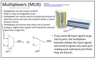
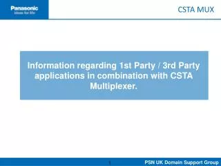
MUX Control Systems. Multiplex Control System. MUX System - Key Features. Designed and tested for continuous operation in 10,000 feet of water Designed for a 20-year service life Designed to minimize maintenance costs, maximize operating time

E N D
MUX System - Key Features • Designed and tested for continuous operation in 10,000 feet of water • Designed for a 20-year service life • Designed to minimize maintenance costs, maximize operating time • Component design is based on 25 years of proven operational experience • Designed and manufactured in accordance with API 16D, API 16E
MUX System Development • One Year $2,000,000 Development Program • All Subsea MUX POD Components were prequalified by Testing at 5,000 psi Ambient Pressure and Low Temperature (+10C/340F) • Subsea MUX POD Electronics Assembly was subjected to Vibration Stress Testing. • Subsea MUX POD was subjected to Hyperbaric Testing at 4,000 psi Ambient Pressure and Low Temperature (+10C/340F)
Electronic System - Key Features • Modular component design • Dual power supplies for each assembly • Control circuits are in a dual redundant distributed system design • Control circuit communications are based on the RS-485 industry standard using the Motorola 68360 chip set. • Each control CPU and MMI CPU is isolated from each other, using 10 Base T for communications. • Embedded data acquisition system which records each event and alarm. • Data logger which includes permanent storage of data acquisition information and maintenance data base.
Embedded Electronics VS PLC • Size and weight of sub sea package. • Minimize heat generated by electronics package • Increased capability • Increased system reliability due to continuous monitoring of key system parameters. • Customized interfaces (i.e. - DP System).
System Software • User interfaces: • Traditional Driller’s panel with lighted push buttons • CCU System monitor with Windows 95 type interface • API Alarms
Operating Systems • Control: VX Works • Display/MMI: Windows NT/95
Control C MMI/Display Visual Basic Surface Communications: Hydril MODBUS Subsea Communications: HAYES Modem Set Programming Languages
CCU • Integrated console with Redundant Stations: • Backup Control • System Monitoring • System Diagnostics • Intuitive design and layout for “at a glance” total system status • Failsafe design / not MMI dependent • Custom Interfaces for: • Electronic riser angle • Riser recoil system • Custom RS-232 or RS-485 inputs/outputs
Driller’s Panel • Micro-processor based / multiplexed with the CCU • Standard packaging for user familiarity • Color coded labeling • Meets hazardous location requirements • API Alarm monitoring • System status monitoring
Subsea Pod • 84 Hydraulic Ports • 96 Functions • 20 Year Design Service Life • Retractable Stab Design for Guide Line and Guide Lineless Operation • E/H Unit and Hydraulic Unit are interchangeable
Subsea Pod E/H Unit Hydraulic Unit
Subsea Pod E/H Unit Sub Sea Electronics Sub Sea MUX Cable Connector Sub Sea Transformer Pressure Compensated Solenoid Housing Shear Seal Pilot Valves Solenoids Pressure Transducers One Atmosphere Base Hydraulic Seal Sub J-Plates
Subsea Pod E/H Unit • All exposed metalic components are manufactured from 316L SS, Nitronics 50/60, or 17-4/7PH. • All penetrations into one atmosphere base have redundant o-ring seals and a test port • All external electrical connectors have redundant o-ring seals with test ports • All electrical wiring subjected to sea pressure has dual pass EPC wiring with boot seal terminations. The wiring assemblies are encased in an oil filled pressure compensated jacket
Shear Seal Pilot Valve • Body constructed of 316L SS and Nitronics 50/60 materials • Seals are Nickel Carbide • Solenoid is rated for 60VDC, 30 watt continuous operation • 65 pound pull in force • 15 pound drop out force
Subsea Pressure Transducer • Body and housing are constructed of 316L SS • Absolute Pressure range of 0 psi to 10,000 psi • Uses measured sea head pressure to determine relative pressure • Unit is interchangeable by removing four bolts
Subsea Electronics Module • Redundant Electronics Modules • Redundant Power Supplies • Low package density • Low power consumption • High Amperage Hypertronic Connectors which are keyed and positive locked
Subsea Pod Hydraulic Unit Reference Accumulators BOP Stack Stab Cylinder SPM Valves Hydraulic Regulators Solid Hydraulic Manifolds Pilot Circuit Hydraulic Filter Shuttle Valves Flow Meter
Subsea Pod Hydraulic Unit • All Subsea POD components are manufactured from 316L SS, Nitronics 50/60, or 17-4/7PH. • Hydril Wedge Block Dynamic Seals (1/2”, 1”, & 1 1/2”) • No Hosing, all hydraulic connections are hard piped or made through the Hydril Stab Block. • Spent BOP fluid is captured to bath all components in the spent fluid instead of sea water. • LMRP Disconnect has a positive read back through a mechanical pin actuated Pilot Valve/Pressure Transducer. • Optional 4 pin wet make/break electrical connector in stab to provide power and signal to stack mounted electronics.
Subsea Hydraulic Regulator • Body and major components are 316L SS and Nitronics 50/60 • Nickel Comaloy Coated Seal Surfaces with Nickel Carbide Seals • 240 GPM Maximum Measured Flow Rate • Dead Band <40 pounds
Subsea SPM Valve • Body, Cage, and Spool Components are Nitronics 50/60 and 316L SS • Springs are Inconel • Three sizes, 1/2” - 1” - 1 1/2” • Low Interflow Cage design • Individual Body Housings manifold mounted • No hose connections, uses dual o-ring SAE Flange connections
Hydraulic Pumping Unit • Stainless Steel Check Valve on Outlet • 1 Quart Surge Bottle • All piping is 316L SS • All hydraulic connections are welded or SAE Flanged • Unit is laid out to maximize maintainability
Hydraulic Filter • Hydraulic Filter rated for 5,000 psi Operating Pressure • 316L and Nitronics 50/60 Construction • 200 psi Automatic By Pass • Multiple size filters available • Same filter assembly is used on Stack and on Surface Hydraulic Power Unit
Accumulator Bottle Rack • 6,000 psi 15 gallon top loading bottles • Available in 10 bottle racks, 12 bottle racks, 16 bottle racks, and 20 bottle racks • Blanking Plates available for odd numbers of bottles in rack • Each manifold can be isolated and has a gauge showing manifold pressure
Accumulator Bottle Rack • Bottle Fluid Port is a Code 62 SAE Dual O-ring connection with four bolt retaining flange • Manifold header is machined from a solid bar of 316L SS • No NPT screwed connections • 316L SS Drip Pan with drain plug