Download
1 / 19
190 likes | 320 Views
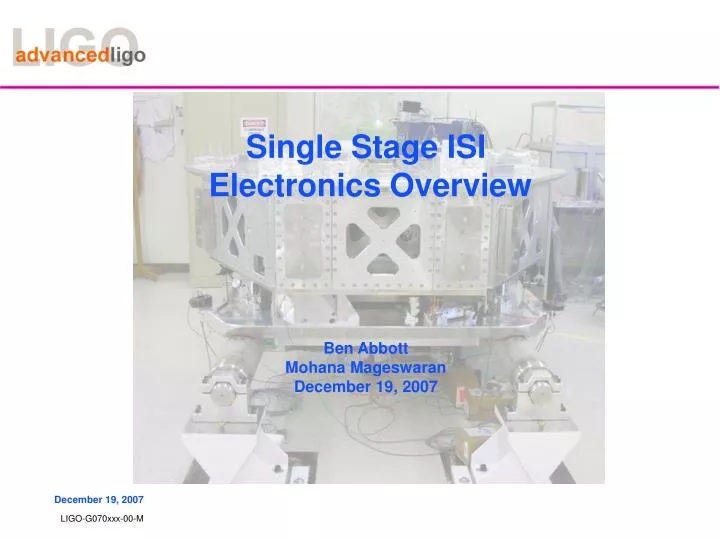
Single Stage ISI Electronics Overview Ben Abbott Mohana Mageswaran December 19, 2007. Single Stage ISI. springs and sensors under the table top. HAM views. access to a vertical sensor. HAM ISI Sensors. HAM 6 Drive. Stage 2 Control at Stanford. Preliminary data. stage 1 motion. HAM req.

E N D
Single Stage ISI Electronics OverviewBen AbbottMohana MageswaranDecember 19, 2007
springs and sensors under the table top HAM views access to a vertical sensor
Stage 2 Control at Stanford Preliminary data stage 1 motion HAM req stage 2 motionw/ feedback isolation stage 2 motionw/ damping
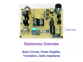
Seismic Isolation Electronics HAM 6 Racks
Seismic Isolation Electronics CDS Electronics Modules • Seven kinds of Electronics modules are needed for the HAM ISI Installation. • Binary I/O Interface • Anti-Image Chassis • Anti-Alias Chassis Rev.7B • STS-2 Interface • ISI Interface Chassis • ISI Coil Driver • Capacitive Position Sensor Field Interface Box • LSU Locker/Unlocker • Some Electronics are shared in the HAM6 rack. • Timing Board • PCIX I/O Chassis • Anti-Alias Chassis Rev.10
Single Stage ISI Interface ISI Interface Block Diagram • Inputs come from 4 GS-13 seismometers, and 4 Capacitive position Sensors. Chassis interfaces signals with ADCs, DACs and Binary I/O modules. • GS-13 Interface has switchable x1 and x10 gain, and two stages of simultaneously switchable whitening with 0.1 Hz zeroes, and 1 Hz poles. • Capacitive Position Interface Card supplies power, and routs signals. It has no gain or filtration.
Seismic Isolation Electronics ISI Information Block Diagram
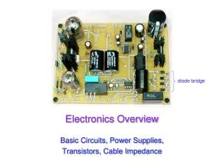
Actuator Electronics The Coarse and Fine actuators used in the ISI are custom manufactured by PSI (Planning Systems Inc.). The coarse actuators are used to actuate in the horizontal and vertical directions at each of the three locations around the HAM. 3. Coarse actuator is capable of generating a continuous force of maximum 20 lb and the Coil Driver is capable of providing the current to produce this force.
Imax = (20 lb) / (6.74 lb/amp) = 3A Vmax = (3 A) * (6.1 ohm) = 18.3 volts (neglect the cable loss)
Noise Specifications The output current noise requirements are most restrictive for the Fine driver and are as follows:
The DAC input is +/- 20 V and noise level is 5µV/sqrt(Hz). • The DAC stage is surrounded by a digital whitening and • analog de whitening filter to address the noise associated with the DAC. • De whitening Filter 2 Poles @ 0.4 Hz and • 2 Zeros @ 15.9 Hz is added to lower the noise • after the differential DAC Input.