Download
1 / 32
320 likes | 321 Views
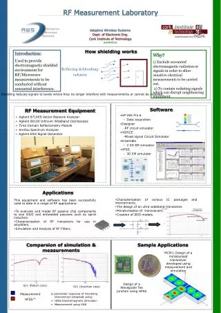
EMMA RF System Carl Beard ASTeC, Daresbury Laboratory. Content. Purpose of the RF System and the challenges faced. Final RF System Design Accelerating Cavity RF Power Source RF Distribution LLRF. Purpose of the RF System Function.

E N D
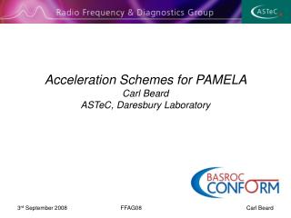
EMMA RF System Carl BeardASTeC, Daresbury Laboratory FFAG08 Carl Beard
Content • Purpose of the RF System and the challenges faced. • Final RF System Design • Accelerating Cavity • RF Power Source • RF Distribution • LLRF FFAG08 Carl Beard
Purpose of the RF System Function • The sole purpose of the RF system is to provide the necessary acceleration to the charged particles. • Since EMMA is a proof of principle device there are a number of parameters that have to be studied • Rapid acceleration through many resonances • Unique longitudinal dynamics • For this reason the RF system has to be flexible and robust • Operate over a finite frequency range • Upgradeable acceleration per turn • Synchronised with ALICE (1.3 GHz) FFAG08 Carl Beard
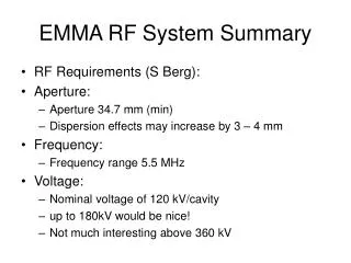
Challenges • Acceleration is achieved with 19 cavities spaced uniformly (mostly) around the ring. • Size – competing constraints -Large beam aperture and narrow cavity vessel reduce cavity efficiency. • Control - Phase and amplitude of each cavity has to be within tight tolerances • Source - Either a large number of RF Sources or a vastly complex distribution scheme required • Energy - Upgradeable for higher acceleration voltage • Bandwidth - Large operating frequency range, challenging for; cavity, RF distribution and RF source. 1st September 2008 FFAG08 Carl Beard
EMMA RF Specification 1st September 2008 FFAG08 Carl Beard
RF Design • Cavity Design Completed • Including RF Power Coupler, Tuner, Cooling, RF Pick-up. • Aluminium Cavity produced to allowed verification of frequency, tuner range, R/Q. • Production Prototype received ready for high power testing • First production cavity batches expected 15th September 2008 • Power coupler contract placed with Times Microwave. • Initial Power coupler failed during bakeout. • First batch of four power couplers received on the 18th August, and are currently being baked. 1st September 2008 FFAG08 Carl Beard
Cavity Design Parameters # Includes Distribution losses and LLRF Control 1st September 2008 FFAG08 Carl Beard
EMMA Cavity Design Final Design Approved November 21, 2007
Test Results Field Charachterisation was carried out with the Bead Pull experimental method. This provided an indication to the cavity efficiency. R/Q of 100 was measured • Aluminium Cavity Measurements • Assisted to redesign tuner • Reduce the cost of the cavity FFAG08 Carl Beard
RF Source • RF source(s) required to provide all the power to the RF cavities. • Number of options available • 19 (5kW) Solid state amplifiers • 1 (>90kW) High Power Klystron/TWT/IOT • A number of smaller IOTs/TWTs • Each system has significant advantages • As part of the tender exercise, each bid was judged on, Technical merit, cost and delivery FFAG08 Carl Beard
RF Source (Cont) • 19 Solid State Amplifier • Each Cavity had individual RF source. • Excellent Amplitude and Phase control • Large bandwidth • No RF Distribution required • 19 LLRF control systems required • Higher cost • Baseline specification voltage only, space and cost limiting upgrade option. FFAG08 Carl Beard
RF Source (Cont) • High Power RF Source • Very high powers available (>100 kW) • Inexpensive compared with SS • Single LLRF control system • RF Distribution to 19 cavities demanding • Limited bandwidth on IOTs and Klystrons • Source failure requires long down time FFAG08 Carl Beard
CPI IOT • Preferred solution to be a 90 kW Amplifier (IOT Based system) solution from CPI • Includes power supply, pre amplifier, control system and cooling system. • Demonstrated adequate bandwidth • Much simpler upgrade option. • Similar technology already in operation on ALICE. • Not the cheapest option for the baseline 120 kV per cavity design • Considerably cheaper upgrade cost • Distribution system required. FFAG08 Carl Beard
CPI IOT test data FFAG08 Carl Beard
RF Distribution • Since the preferred RF Source was the CPI Amplifier • Distribution scheme required to transfer power from single RF source to 19 RF cavities • Tender exercise provide several solutions • Very little technical merit between compliant systems. • Final system design was based on the Hybrid (Cascaded solution) from Q-Par Angus. FFAG08 Carl Beard
Cascaded Distribution Scheme Load Circulator 7dB 6dB 3dB 4.8dB Tube 3-Stub Tuner • The same regardless of number of splits. • Compact System 1st September 2008 FFAG08 Carl Beard
Physical Layout Problem Matching the phase of the cavities with a synchronous particle. Transit time of particle = 2.63 ns = 3.419 RF Cycles 151° Phase 1st September 2008 FFAG08 Carl Beard
Phase Assessment Phase Difference between 2 ports is 90° +/- 90° Phase adjustment possible with 3-stubb tuners 3 dB Coupling 50% Power to Cavity 4.8 dB Coupling 33% Power to Cavity Equal power delivered to each port. 1st September 2008 FFAG08 Carl Beard
Phase Difference Modelled Final waveguide components will be matched at 1.3 GHz, 3-stub tuners will be adopted to adjust away from the baseline 1st September 2008 FFAG08 Carl Beard
Q-Par Design • Scheme proposed by Q-Par Angus • Reduced overall size • Untested for high powers/voltages • Prototype will be required prior to production manufacture
Operational Control Challenges • The LLRF feedback will be responsible for control of overall system phase and amplitude • This is typically based on a feedback system that controls the drive signal to the generator • Typically at low power, hence Low-Level RF. • System is limited due to having a single source driving 19 cavities • FPGA Based - Digital vector sum capability required. 1st September 2008 FFAG08 Carl Beard
Operational Control Challenges 2 • Implication of altering RF Frequency • Ideal operating phase dependant on frequency • Phase adjustors used to match the waveguide electrical length with the flight time of the particles • Calibration of phase adjustor to systematically change the operational frequency • LLRF system will respond differently further away from the MO signal • Modelling of the LLRF system (feedback loops) required to determine achievable phase and amplitude conditions 1st September 2008 FFAG08 Carl Beard
EMMA LLRF • Needs to control all 19 cavities from a single amplifier • Vector sum capability required! • Consulted Dmitry Teytelman (ex-SLAC), now DimTel Inc. for LLRF solutions for EMMA • Solution proposed will utilise the SNS LLRF architecture developed by Larry Doolittle at LBNL: • “The SNS Front End LLRF System”, L Doolittle et al, LINAC2002, Korea. • System has been developed to match ILC requirements of 0.01o and 0.01% in phase and amplitude performance: • “Digital Low-Level RF Control Using Non-IQ Sampling”, L Doolittle et al, LINAC2006, Knoxville. 1st September 2008 FFAG08 Carl Beard
EMMA Requirements • Need to study the RF feedback requirements. • Modelling of the feedback loops. • Assess system response to disturbances. • Determine loops gains and group delay limitations. • Fundamentally define EMMA system specification. 1st September 2008 FFAG08 Carl Beard
LLRF Distribution Phase Shifter SS Amp Amplitude Control Master Oscillator Tube Comparator Level Detector Comparator Mixer • For an accelerator RF system we have: • The device, an RF cavity. • Actuator - klystron. • Sensor - cavity probe. • Controller – LLRF module. • Separate Amplitude and Phase. 1st September 2008 FFAG08 Carl Beard
LLRF Control Simulations • Included: • Tuneable LLRF controller; • ADC quantization and noise; • IOT frequency response; • IOT saturation; • IOT gain modulation by power supply; • Cavity frequency estimation. • Not implemented: • Beam loading; • IOT phase shift modulation by power supply; • Signal path filters; • Automatic vector sum setup. 1st September 2008 FFAG08 Carl Beard
Optimum Case (No Frequency Offset, No Error) • Simulate for 100 μs to save time. • Station setpoint 840 kV, −10 degrees. • Feedback turn-on is well controlled, settling by 40 μs. • Residual errors 0.004 % amplitude, 0.002 phase. 1st September 2008 FFAG08 Carl Beard
Errors introduced (worst case) • Frequency Offset -4 MHz, • 10 kHz Cavity Tuning Errors, • HVPS Ripple • 1% HVPS ripple at 2 kHz. • Longer pulse simulated to • map out the response. • Residual errors 0.1 % • amplitude, 0.05 phase. 1st September 2008 FFAG08 Carl Beard
Summary • Cavity High Power Test being prepared • Production cavities on schedule • RF Source – Contract Placed with CPI • Single 90 kW IOT • RF Distribution • Waveguide approach adopted, Contract placed with Q-Par Angus • Proposed Hybrid System • LLRF System • Simulations suggest specification can be achieved • Boards now under development 1st September 2008 FFAG08 Carl Beard