Download
1 / 34
380 likes | 951 Views
Fundamentals of Multimedia Chapter 8 Lossy Compression Algorithms Ze-Nian Li and Mark S. Drew. 건국대학교 인터넷미디어공학부 임 창 훈. Outline. 8.1 Introduction 8.2 Distortion Measures 8.3 The Rate-Distortion Theory 8.4 Quantization 8.5 Transform Coding. 8.1 Introduction.

E N D
Fundamentals of MultimediaChapter 8Lossy Compression AlgorithmsZe-Nian Li and Mark S. Drew 건국대학교 인터넷미디어공학부 임 창 훈
Outline 8.1 Introduction 8.2 Distortion Measures 8.3 The Rate-Distortion Theory 8.4 Quantization 8.5 Transform Coding Li & Drew; 건국대학교 인터넷미디어공학부 임창훈
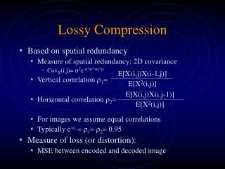
8.1 Introduction • Lossless compression algorithms do not deliver • compression ratios that are high enough. • Hence, most multimedia compression algorithms • are lossy. • What is lossy compression ? • The compressed data is not the same as the • original data, but a close approximation of it. • Yields a much higher compression ratio than • that of lossless compression. Li & Drew; 건국대학교 인터넷미디어공학부 임창훈
8.2 Distortion Measures • The three most commonly used distortion measures in image compression are: • mean square error (MSE) σ2, xn : input data sequence yn : reconstructed data sequence N : length of data sequence Li & Drew; 건국대학교 인터넷미디어공학부 임창훈
Signal to noise ratio (SNR), in decibel units (dB) σ2x : average square value of original data sequence σ2d : MSE • Peak signal to noise ratio (PSNR), in decibel units (dB) • For 8 bit image (video), xpeak = 255 Li & Drew; 건국대학교 인터넷미디어공학부 임창훈
8.3 The Rate-Distortion Theory • Tradeoffs between Rate and Distortion (R-D). Fig. 8.1: Typical Rate Distortion Function. Li & Drew; 건국대학교 인터넷미디어공학부 임창훈
8.4 Quantization • Reduce the number of distinct output values to • a much smaller set. • Main source of the loss in lossy compression. • Three different forms of quantization. • - Uniform: midrise and midtread quantizers. • Non-uniform: companded (compress/expanded) • quantizer. • - Vector Quantization (VQ). Li & Drew; 건국대학교 인터넷미디어공학부 임창훈
Uniform Scalar Quantization • A uniform scalar quantizer partitions the domain of • input values into equally spaced intervals. • The output or reconstruction value corresponding • to each interval is taken to be the midpoint of the • interval. • The length of each interval is referred to as the • step size, denoted by the symbol Δ. Li & Drew; 건국대학교 인터넷미디어공학부 임창훈
Uniform Scalar Quantization • Two types of uniform scalar quantizers: • Midrise quantizers have even number of output • levels. • Midtreadquantizers have odd number of output • levels, including zero as one of them Li & Drew; 건국대학교 인터넷미디어공학부 임창훈
Uniform Scalar Quantization • For the special case where Δ= 1, we can simply compute the output values for these quantizers as: Li & Drew; 건국대학교 인터넷미디어공학부 임창훈
Uniform Scalar Quantization • Performance of an Mlevel quantizer. Let B = {b0, b1, … , bM} be the set of decision boundaries and Y = {y1, y2, … , yM} be the set of reconstruction or output values. • Suppose the input is uniformly distributed in the interval [−Xmax, Xmax]. The rate of the quantizer is: Li & Drew; 건국대학교 인터넷미디어공학부 임창훈
Fig. 8.2: Uniform Scalar Quantizers: (a) Midrise, (b) Midtread. Li & Drew; 건국대학교 인터넷미디어공학부 임창훈
Quantization Error of Uniformly Distributed Source • Since the reconstruction values yiare the midpoints • of each interval, the quantization error must lie • within the values [−Δ/2, Δ/2]. For a uniformly distributed source, the graph of the quantization error is shown in Fig. 8.3. Li & Drew; 건국대학교 인터넷미디어공학부 임창훈
Fig. 8.3: Quantization error of a uniformly distributed source. Li & Drew; 건국대학교 인터넷미디어공학부 임창훈
Vector Quantization • According to Shannon's original work on information • theory, any compression system performs better if it • operates on vectors or groups of samples rather than • individual symbols or samples. • Form vectors of input samples by simply concatenating • a number of consecutive samples into a single vector. • Instead of single reconstruction values as in scalar • quantization, in VQ, code vectors with ncomponents • are used. • A collection of these code vectors form the codebook. Li & Drew; 건국대학교 인터넷미디어공학부 임창훈
Vector Quantization Fig. 8.5: Basic vector quantization procedure. Li & Drew; 건국대학교 인터넷미디어공학부 임창훈
8.5 Transform Coding • The rationale behind transform coding: If Y is the result of a linear transform T of the input vector X in such a way that the components of Y are much less correlated, then Y can be coded more efficiently than X. • If most information is accurately described by the first few components of a transformed vector, then the remaining components can be coarsely quantized, or even set to zero, with little signal distortion. Li & Drew; 건국대학교 인터넷미디어공학부 임창훈
Spatial Frequency and DCT • Spatial frequency indicates how many times pixel values change across an image block. • The DCT formalizes this notion with a measure of how much the image contents change in correspondence to the number of cycles of a cosine wave per block. • The role of the DCT is to decompose the original signal into its DC and AC components; the role of the IDCT is to reconstruct (re-compose) the signal. Li & Drew; 건국대학교 인터넷미디어공학부 임창훈
Definition of DCT • f(i,j): spatial domain values • F(u,v): (spatial) frequency domain values frequency values • i, u: 1, …, M, j, v: 1, …, N Li & Drew; 건국대학교 인터넷미디어공학부 임창훈
2D Discrete Cosine Transform (2D DCT) i, j, u, v: 0, 1, …,7 Li & Drew; 건국대학교 인터넷미디어공학부 임창훈
2D Inverse Discrete Cosine Transform (2D IDCT) i, j, u, v: 0, 1, …,7 Li & Drew; 건국대학교 인터넷미디어공학부 임창훈
1D Discrete Cosine Transform (1D DCT) i, u: 0, 1, …,7 Li & Drew; 건국대학교 인터넷미디어공학부 임창훈
1D Inverse Discrete Cosine Transform (1D IDCT) i, u: 0, 1, …,7 Li & Drew; 건국대학교 인터넷미디어공학부 임창훈
The 1D DCT basis functions. Li & Drew; 건국대학교 인터넷미디어공학부 임창훈
The 1D DCT basis functions. Li & Drew; 건국대학교 인터넷미디어공학부 임창훈
The Examples of 1D Discrete Cosine transform: (a) A DC signal f1(i), (b) An AC signal f2(i). Li & Drew; 건국대학교 인터넷미디어공학부 임창훈
Examples of 1D Discrete Cosine Transform: (c) f3(i) = f1(i) + f2(i), (d) an arbitrary signal f(i). Li & Drew; 건국대학교 인터넷미디어공학부 임창훈
An example of 1D IDCT. Li & Drew; 건국대학교 인터넷미디어공학부 임창훈
An example of 1D IDCT. Li & Drew; 건국대학교 인터넷미디어공학부 임창훈
DCT is Linear Transform • In general, a transform T (or function) is linear, iff • where α and β are constants, p and q are any • functions or variables. • This property can readily be proven for the DCT because it uses only simple arithmetic operations. Li & Drew; 건국대학교 인터넷미디어공학부 임창훈
Cosine Basis Functions • Function Bp(i) and Bq(i) are orthogonal, if • Function Bp(i) and Bq(i) are orthonormal, • if they are orthogonaland Li & Drew; 건국대학교 인터넷미디어공학부 임창훈
Cosine Basis Functions • It can be shown that: Li & Drew; 건국대학교 인터넷미디어공학부 임창훈
Graphical Illustration of 8×8 2D DCT basis. Li & Drew; 건국대학교 인터넷미디어공학부 임창훈
2D Separable Basis • The 2D DCT can be separated into a sequence of two, 1DDCT steps: • This simple change savesmany arithmetic steps. • The number of iterations required isreduced • from 8×8 to 8+8. Li & Drew; 건국대학교 인터넷미디어공학부 임창훈