Download
1 / 21
210 likes | 337 Views
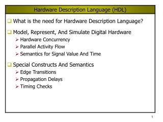
HARDWARE DESCRIPTION LANGUAGE (HDL). What is HDL?. A type of programming language for sampling and modeling of electronic & logic circuit designs It can describe the circuit’s operation, design and organization By using CAD tools, it can be used for test and verify through simulations

E N D
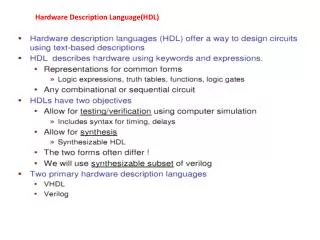
What is HDL? • A type of programming language for sampling and modeling of electronic & logic circuit designs • It can describe the circuit’s operation, design and organization • By using CAD tools, it can be used for test and verify through simulations • Also used to model the intended piece of device like ASICs, FPGAs CPLDs and others • Various kinds : VHDL, Verilog HDL, AHDL etc
Why HDL? • Software solution due to limits in hardware solutions and to: • Increasing design complexity • Increasing cost in time and investment • Increasing knowledge requirement • Inadequacy of other existing languages • Text-based rather than schematic design • faster time-to-market • synthesis and analysis • Documentation
Intro to VHDL • VHSIC Hardware Description Language • VHSIC stands for Very High Speed Integrated Circuit • Jointly developed in 1983 by Intermetrics, IBM & Texas Instruments • Initially used by the US Dept. of Defence • IEEE Standard in 1987 then enhanced and restandardized in 1993
Using VHDL as UniMAP’sOBE and PBL • Near-approach to industry • High density electronic design • Multidisciplinary – electronics, microelectronics, communications, instrumentations and control • Technology related • Reconfigurable • Actual implementation • System Design • System throughput recognition • problem solving ability • debugging techniques
VHDL Main Features Behavior Dataflow Timing Structure
VHDL Architectures • Does not allow a layout description Abstraction Levels VHDL Architectures Algorithmic How it works FSM Behavioral RTL Structural How it is connected Gate Layout
A Dataflow Language CONTROLFLOW DATAFLOW EX: C language assignment EX: VHDL signal assignment X = A & B; X <= A and B; X is computed out of A and B ONLY each time this assignment isexecuted A PERMANENT link is created between A, B, and X X is computed out of A and B WHENEVER A or B changes
A Dataflow Language (cont’d) CONTROLFLOW DATAFLOW EX: C language assignment EX: VHDL signal assignment X = A & B; ------ X = C & D; X <= A and B; ------ X <= C and D; • NO • YES
Behavioral vs Structural process (a,b,cin) behavioral begin s <= (a xor b) xorcin; c <= ((a xor b) and cin) or (a and b); end process; • Full Adder -- component declarationstructural component FA port ( inA, inB, inC : in std_logic; Sum, Carry : out std_logic ); end component; -- component instantiation U1 : FA port map : (a=>inA, b=>inB, c=>inC, s=>Sum, c=>Carry);
VHDL WRITTEN FORMAT Library / Package Declaration Entity Declaration Architecture Flow
LIBRARY / PACKAGE DECLARATION Library ieee; Use ieee.std_logic_1164.all; Use ieee.std_logic_signed.all; Use ieee.std_logic_unsigned.all; Use ieee.std_logic_arith.all; Library work; Use work.my_package.entity_name; Use work.my_package.function_name;
ENTITY DECLARATION • Specifies the input and output signals of the entity • modes : in, out, inout, buffer • Format : Entity name is port (port_name : mode data_type); End name;
Rules for Entity Name • Any alphanumeric character may be used in the name, as well as the ‘_’ underscore character. • It is not case sensitive • Cannot be a VHDL keyword • Cannot begin with a number, must begin with a letter • Cannot have 2 straight ‘_ _’ underscores • Cannot end with an ‘_’ underscore • Cannot have a blank space
Common Data Type • Std_logic data : bit logic, Std_logic_vector (b downto a) or Std_logic_vector (a to b) : array of bit logic • Legal values for std_logic : 0,1,Z,-,L,H,U,X,W • Only the first 4 are used in synthesis • Signed, Unsigned • Integer • Boolean
Example Full Adder A SUM B Cout Cin 4 bit Full Adder A[3..0] SUM[3..0] B[3..0] Cout Cin
ARCHITECTURE • The Internal Aspect of a Design Unit • Can be behavioral (RTL) or structural • Always associated with single entity • Single entity can have multiple architectures architecturearchitecture_name ofentity_name is {architecture_declarative_part} begin {architecture_descriptive_part} end[architecture_name];
Two architecture flavors: Behavioral & Structural Behavioral architecture ONE of MUX2 is begin YOUT <= (AIN and not SIN) or (BIN and SIN); end ONE; Structural architecture TWO of MUX2 is component MX2 -- a macro from a library port (A, B, S:in std_logic; Y :out std_logic); end component; begin -- instantiate MX2 U1: MX2 port map(A=>AIN, B=>BIN, S=>SIN, Y=>YOUT); end TWO; Declarative part Descriptive part
ARCHITECTURE DATA OBJECTS • 3 kinds of data object : • Signal • Constant • Variable • Signal is the most common form of data object used in describing the logic signals (wires) in a circuit • The value of an individual signal is described in apostrophes • The value of multiple signal is described in double quotes