Download
1 / 15
150 likes | 349 Views
ECE 353 Computer Systems Lab I Verilog Hardware Description Language. HDL Overview. Hardware description languages (HDL) offer a way to design circuits using text-based descriptions HDL describes hardware using keywords and expressions. Representations for common forms

E N D
ECE 353Computer Systems Lab IVerilogHardware Description Language
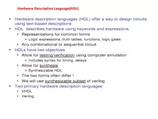
HDL Overview • Hardware description languages (HDL) offer a way to design circuits using text-based descriptions • HDL describes hardware using keywords and expressions. • Representations for common forms • Logic expressions, truth tables, functions, logic gates • Any combinational or sequential circuit • HDLs have two objectives • Allow for testing using computer simulation • Includes syntax for timing • Allow for synthesis • Synthesizable HDL • The two forms often differ • We will use synthesizable subset of verilog • Two primary hardware description languages • VHDL • Verilog
Hardware Description Language - Verilog Represents hardware structure and behavior Logic simulation -> generates waveforms //HDL Example 3-1 //-------------------------- module smpl_circuit(A,B,C,x,y); input A,B,C; output x,y; wire e; and g1(e,A,B); not g2(y, C); or g3(x,e,y); endmodule Detect errors before fabrication
Verilog Keywords and Syntax Lines that begin with // are comments (ignored by simulation) About 100 keywords in total Syntax allows logic to be described precisely Keywords are case sensitive //HDL Example 3-1 //-------------------------- module smpl_circuit(A,B,C,x,y); input A,B,C; output x,y; wire e; and g1(e,A,B); not g2(y, C); or g3(x,e,y); endmodule
module, input, and outputkeywords module: Building block in Verilog Always terminated with endmodule module followed by circuit name and port list Each port is either an input or output //HDL Example 3-1 //-------------------------- module smpl_circuit(A,B,C,x,y); input A,B,C; output x,y; wire e; and g1(e,A,B); not g2(y, C); or g3(x,e,y); endmodule
wireand gate-level keywords wire defines internal circuit connections Each gate (and, or, not) defined on a separate line Gate I/O includes wires and port values Note: each gate is instantiated with a name (e.g. g1) //HDL Example 3-1 //-------------------------- module smpl_circuit(A,B,C,x,y); input A,B,C; output x,y; wire e; and g1(e,A,B); not g2(y, C); or g3(x,e,y); endmodule
Modeling Circuit Delay • Timescale directive indicates units of time for simulation • ‘timescale 1ns / 100ps • #(30) indicates an input to output delay for gate g1 of 30 ns • #(10) indicates an input to output delay for gate g2 of 10 ns //HDL Example 3-2 //--------------------------------- //Description of circuit with delay module circuit_with_delay (A,B,C,x,y); input A,B,C; output x,y; wire e; and #(30) g1(e,A,B); or #(20) g3(x,e,y); not #(10) g2(y,C); endmodule
//HDL Example 3-3//---------------------- //Stimulus for simple circuitmodule stimcrct;reg A,B,C;wire x,y;circuit_with_delay cwd(A,B,C,x,y);initial begin A = 1'b0; B = 1'b0; C = 1'b0; #100 A = 1'b1; B = 1'b1; C = 1'b1; #100 $finish; endendmodule//Description of circuit with delay module circuit_with_delay (A,B,C,x,y); input A,B,C; output x,y; wire e; and #(30) g1(e,A,B); or #(20) g3(x,e,y); not #(10) g2(y,C);endmodule Test bench Stimulus circuit_with_delay is instantiated Reg keyword indicates that values are stored (driven) Stimulus signals are applied sequentually $finish indicates simulation should end Result is a collection of waveforms
Test bench Stimulus • Timescale directive indicates units of time for simulation • ‘timescale 1ns / 100ps • Note that input values change at 100ns • Shaded area at left indicates output values are undefined
//HDL Example 3-4//------------------------------ //Circuit specified with Boolean equationsmodule circuit_bln (x,y,A,B,C,D); input A,B,C,D; output x,y; assign x = A | (B & C) | (~B & C); assign y = (~B & C) | (B & ~C & ~D);endmodule Specifying Boolean Expressions • assign keyword used to indicate expression • Assignment takes place continuously • Note new symbols specific for Verilog • OR -> | • AND -> & • NOT -> ~
//HDL Example 3-5//----------------------------------- //User defined primitive(UDP) primitive crctp (x,A,B,C); output x; input A,B,C;//Truth table for x(A,B,C) = Minterms (0,2,4,6,7) table// A B C : x (Note that this is only a comment) 0 0 0 : 1; 0 0 1 : 0; 0 1 0 : 1; 0 1 1 : 0; 1 0 0 : 1; 1 0 1 : 0; 1 1 0 : 1; 1 1 1 : 1; endtable endprimitive User Defined Primitives Allows definition of truth table Only one output allowed
//HDL Example 4-3//---------------------------------------------- //Dataflow description of a 2-to-4-line decoder //See Fig.4-19module decoder_df (A,B,E,D); input A,B,E; output [0:3] D; assign D[0] = ~(~A & ~B & ~E), D[1] = ~(~A & B & ~E), D[2] = ~(A & ~B & ~E), D[3] = ~(A & B & ~E);endmodule More Verilog Examples • Combinational functionality • All assignments take place at the same time • Note declaration of a bus • output [0:3] D;
//HDL Example 4-5//----------------------------------- //Dataflow description of a 4-bit comparator.module magcomp (A,B,ALTB,AGTB,AEQB); input [3:0] A,B; output ALTB,AGTB,AEQB; assign ALTB = (A < B), AGTB = (A > B), AEQB = (A == B);endmodule More Verilog Examples • Easy to define arithmetic functionality • Each comparison creates a single bit result • Synthesizer automatically converts RTL description to gate-level description • RTL -> register transfer level
//HDL Example 4-7//--------------------------------- //Behavioral description of 2-to-1-line multiplexermodule mux2x1_bh(A,B,select,OUT); input A,B,select; output OUT; reg OUT; always @ (select or A or B) if (select == 1) OUT = A; else OUT = B;endmodule More Verilog Examples Conditional statements (if, else) allow for output choices always keyword used to indicate action based on variable change Generally conditional statements lead to multiplexers
Summary • Hardware description languages provide a valuable tool for computer engineers • Any logic circuit (combinational or sequential) can be represented in HDL • Circuits created using keywords and syntax • Possible to use timing information • Specify time scale • Gate and RTL descriptions are possible • Verilog is widely used in industry • Mention it at your job interviews!