Download
1 / 23
230 likes | 365 Views
Cryogenic System for Superconducting Final Focus Magnets (SCFFM) at ATF-2. N. KIMURA, T. TOMARU, Y. AJIMA, T. KUME, A. YAMAMOTO, K. TSUCHIYA and T. TAUCHI. OUTLINE Proposed cooling scheme for SCFFM for 4K Connection Box Vibration control Heat load estimation

E N D
Cryogenic System for Superconducting Final Focus Magnets (SCFFM) at ATF-2 N. KIMURA, T. TOMARU, Y. AJIMA, T. KUME, A. YAMAMOTO, K. TSUCHIYA and T. TAUCHI
OUTLINE • Proposed cooling scheme for SCFFM for 4K Connection Box • Vibration control • Heat load estimation • Set up plan for the cryostat in the ATF-2 • Proposed schedule for construction plan • Summary
Infrastructures at ATF2 • Infrastructures at ATF2 LHe supply Very limited (supplied only by dewar, from Cryogenics Science Center) Cryogenics facility None Space for Liquefier around ATF ?? GHe recovery line Yes Human resource for cryogenics operation None Power supplies for SC magnets None We would like to propose our plan which can be operated under limited infrastructures at ATF2!! and can be consistent with BNL’s magnet cooling design.
Proposed the cryogenics system at KEK • Cooling scheme @ ATF2 • We propose to construct “A re-condensation cooling type” with low vibration Cryo-coolers. • Vibration Control -> Mixture of LCGT scheme & SCGR scheme A R&D work of low vibration cryogenics system have just started in Cryogenics Science Center as a basic research for this kind of project.
Example of Ultra-low Vibration Pulse tube cryo-cooler system at KEK This system was originally developed for gravitational wave detector. Vibration level of the system was almost the same as that in Kamiokamine. Vibration level is ~1nm@1Hz (Bin width~0.01) When the cryo-cooler uses as a re-condensation cooler, do not need vibration reduction stage in above figure. Point is separated Rotary valve from cold-head. By courtesy of Dr. T. Tomaru (KEK) This system was presented at ICC13.
Example of Superconducting Gravimeter Sensitivity Restrain boiling type by using cooler (Baby sitter, re-condensation, thermo siphon) Cold Head Support Gravimeter He dewar Leveler
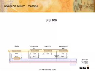
Cooling scheme for 4K connection box at ATF2 Heat loads by Current leads into 4K level 300A x 4 leads (0.6 W, 0.15W/lead) by HTC conductor 20A x 10 leads (Total 0.56 W, 0.056W/lead) by Low RRR Cu One 1.3W/4.2K Plus tube type cryocooler as 20K cooler Two 1.3W/4.2K Plus tube type cryo-coolers use as re-condensation cooler Three Plus tube type cryocooler will be mounted with low vibration mounting Tubes for pre-cooling and thermo siphon mode KEK’s design responsibility
Proposed the cryogenics system at KEK • Cooling scheme @ ATF2 • We propose to construct “A re-condensation cooling type” with low vibration Cryo-coolers. • Vibration Control -> Mixture of LCGT scheme & SCGR scheme A R&D work of low vibration cryogenics system have just started in Cryogenics Science Center as a basic research for this kind of project.
Estimated heat loads at 4K connection box Two 1.3W/4.2K Plus tube type cryo-coolers use for re-condensation coolers One 1.3W/4.2K Plus tube type cryocooler as 20K cooler < 1.5~2.4 W by magnets Not enough Enough for radiation cooing Cooling performance for magnet cryostat
OUTLINE • Proposed cooling scheme for SCFFM for 4K Connection Box • Vibration control • Heat load estimation • Set up plan for the cryostat in the ATF-2 • Proposed schedule for construction plan • Summary
Proposed set up plan in the tunnel at ATF2 For working and walking space This is good solution at ATF2! 4K connection box Advantage one. Easy maintenance of cryogenics part due to the outside of radiation control area! Bellows part connection tube Beam direction Shintake monitor Advantage Two. Huge of mass of shield block will be attached with the BOX, and it will be reduced mechanical resonances.
OUTLINE • Proposed cooling scheme for SCFFM for 4K Connection Box • Vibration control • Heat load estimation • Set up plan for the cryostat in the ATF-2 • Proposed schedule for construction plan • Summary
OUTLINE • Proposed cooling scheme for SCFFM for 4K Connection Box • Vibration control • Heat load estimation • Set up plan for the cryostat in the ATF-2 • Proposed schedule for construction plan • Summary
Summary • Re-condensation cooling system @ ATF2 are proposed by KEK. • R&D work for low vibration cryogenics have been accepted in Cryogenics Science Center as a basic research. • For reducing vibration level lower than 50 nm, we may contribute to the low vibration cryocooler system design to be adaptable to the BNL magnet design in cooperation to the design. • Final goal for the ready to operation in ATF-2 is the end of October 2013.
Open to Discussion • R&D? • Other part for Contributions? • Support system? • Vibration? • Etc?
Design work for 4K box at KEK • Structure of Current Leads For B1 & B3 magnets -> HTC + L.R3.Cu lead For left five magnets -> hybrid conductor type like LHC sc-corrector magnet • Cryo-coolers -> Plus tube cryocooler • Cooling scheme -> Re-condensation cryogenic system Mixture of LCGT scheme & SCGR scheme
Estimated Heat load by Current Leads-Case 1 Set-up: consists of L.R3. Cu & HTC 300K->77K leads: Low-R3 Cu 77K->20K leads: Low-R3 Cu 20K-> 4K leads: HTC 300K->77K calculation was based on Wiedemann-Franz law. Roughly ~50W/kA
Estimated Heat load by Current Leads-Case 2 Set-up: consists of hybrid Cu 300K->77K leads: hybrid Cu 77K-> 20K leads: hybrid Cu 20K-> 4K leads: hybrid Cu (Except B1 and B3 leads)
Example of Connection Box with Cryocooler and C. Leads at SKS Cryo-coolers C. Leads Cryo-cooler for C. Leads Connection tube
Example of the cryostat with CRYOMECH PT Photo: Polar Bear Experiment system by UCB
Compressor Valve Regenerator Displacer Superconducting Magnet for Solar Axion Search @ ICEPP U-Tokyo • Dipole field of 10 T•m • Cooled by using cryo-coolers (2 W at 4.2 K). Cryo-cooler Race Track Coils (5 T x 2m)