Download
1 / 21
210 likes | 292 Views
Linear Collider Bunch Compressors. Andy Wolski Lawrence Berkeley National Laboratory USPAS Santa Barbara, June 2003. Outline. Damping Rings produce “long” bunches

E N D
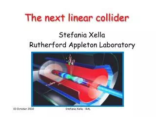
Linear Collider Bunch Compressors Andy Wolski Lawrence Berkeley National Laboratory USPAS Santa Barbara, June 2003
Outline • Damping Rings produce “long” bunches • quantum excitation in a storage ring produces longitudinal emittance that is relatively large compared to some modern particle sources • long bunches tend to reduce the impact of collective effects • large momentum compaction rapidly decoheres modes • the longer the bunch, the lower the charge density • bunch lengths in damping rings are ~ 5 mm • Main Linacs and Interaction Point require “short” bunches • of the order 100 µm in NLC, 300 µm in TESLA • Main issues are: • How can we achieve bunch compression? • How can we compensate for the effects of nonlinear dynamics? • What are the effects of (incoherent and coherent) synchrotron radiation?
NLC Bunch Compressor (First and Second Stages) Schematic Layout (NLC) • Essential components of a bunch compression system include: • RF power • “Phase Slip”: variation of path length with energy NLC Bunch Compressor (First Stage)
VRF t Basic Principles • A “rotation” of longitudinal phase space…
Lets do some maths… • We would like to know • how much RF power • how much wiggler (or chicane, or arc) are needed to achieve a given compression • We consider the changes in the longitudinal phase space variables of a chosen particle in each part of the compressor • The RF section changes only the energy deviation: • In a linear approximation, we can write:
Lets do some maths… • The wiggler (or arc) changes only the longitudinal co-ordinate: • Again in a linear approximation: • The full transformation can be written:
Optimum Compression • Since the transformation is symplectic (in the case of no acceleration from the RF) the longitudinal emittance is conserved • For a given value of R65, the best compression that can be achieved is: • This optimum compression is obtained with:
Limitations on Compression • For final bunch length << initial bunch length, we can make the approximations: • Clearly, we can make the final bunch length shorter simply by • increasing the RF voltage, and/or • increasing the RF frequency • and adjusting R56 appropriately. • In practice, the compression that can be achieved is limited by: • available RF power • increase in energy spread of the bunch (emittance is conserved) • nonlinear dynamics, CSR etc.
Bunch compression in TESLA. The pictures show the initial (left) and final (right) longitudinal phase space, excluding (red) and including (black) the nonlinear phase slip terms. Nonlinear Effects • So far, we have made linear approximations for • the energy change variation with position in bunch (in the RF section) • the path length variation with energy (in the wiggler or arc), also known as nonlinear phase slip • The nonlinear phase slip is dependent on the linear slip • for an arc, T566 1.9R56 • for a chicane or wiggler, T566 -1.5R56
Nonlinear Effects • The nonlinear phase slip introduces a strong correlation between z and 2 • Since the phase space is rotated by ~ /2, we can compensate this with a correlation between and z2 at the start of the compressor • Note that the energy map (for a general RF phase) looks like: • Choosing an appropriate value for the RF phase introduces the required correlation between and z2 to compensate the nonlinear phase slip
Compensation of Nonlinear Phase Slip • An expression for the RF phase required to compensate the nonlinear phase slip can be found as follows: • calculate the complete map for the bunch compressor up to second order in the phase space variables • select the coefficient of 2 in the expression for z, and set this to zero • We find that the required RF phase is given by: • The optimum (linear) phase slip is now given by:
Compensation of Nonlinear Phase Slip - TESLA Entrance of Bunch Compressor After RF After RF and chicane
Two-Stage Compression • The NLC uses a two-stage bunch compressor: • Stage 1 at low energy (1.98 GeV), bunch length reduced from ~ 5 mm to 500 µm • Stage 2 at higher energy (8 GeV), bunch length reduced to ~ 110 µm • Advantages: • Acceleration provides adiabatic damping of energy spread, so the maximum energy spread anywhere in the system is less than 2% • High frequency RF can be used in Stage 2, where the bunch length is already short • Disadvantage: • More complex, longer system
Two-Stage Compression in NLC • Phase errors at the entrance to the main linac are worse than energy errors • Energy error becomes adiabatically damped in the linac • Phase error at the entrance leads to large energy error at the exit • First stage rotates longitudinal phase space ~ /2 • Energy of beam extracted from Damping Rings is very stable • Phase errors from beam loading in the damping ring become energy errors at the exit of the first stage of bunch compression • Second stage rotates phase space by 2 • Energy errors from imperfect beam loading compensation in the prelinac stay as energy errors
Two-Stage Compression in NLC • How do we achieve compression with a rotation through 2? • NLC Stage 2 compressor uses a sequence of systems: • RF • arc • RF • chicane
Longitudinal Phase Space Telescope • The linear map for the NLC Stage 2 compressor is as follows: • With appropriate choices for the parameters: this can be written:
Effects of Synchrotron Radiation • Synchrotron radiation is emitted in the arcs or wiggler/chicane used to provide the phase slip in a bunch compressor • Effects are: • Transverse emittance growth • Increase in energy spread • For very short bunches at low energy, coherent synchrotron radiation (CSR) may be more of a problem than incoherent synchrotron radiation • Weaker bending fields produce less radiation, and therefore have less severe effects • CSR may also be limited by “shielding” the radiation using a narrow aperture beam pipe
Incoherent Synchrotron Radiation • Transverse and longitudinal emittance growth is analogous to quantum excitation in storage rings • Transverse emittance growth is given by: • The energy loss from incoherent synchrotron radiation is: • The increase in energy spread is given by:
Coherent Synchrotron Radiation • A bunch of particles emits radiation over a wide spectrum • For regions of the spectrum where the radiation wavelength is much less than the bunch length, the emission is incoherent • for a bunch of N particles, radiation power N • Where the radiation wavelength is of the order of or longer than the bunch length, the bunch emits as a single particle • radiation power N2 • Since N is of the order 1010, the coherence of the radiation represents a significant enhancement • The radiation acts back on the beam, leading to a correlated energy spread within the bunch