Download
1 / 15
150 likes | 394 Views
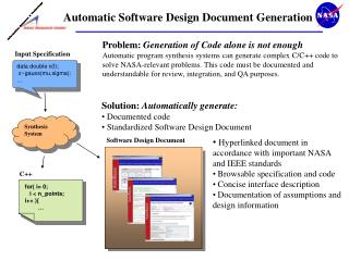
The Automatic Generation of Merged-Mode Design Constraints. Subrangshu K. Das, Texas Instruments Ajay J. Daga, FishTail Design Automation Aishwarya Singh, Texas Instruments Vikas Sachdeva, FishTail Design Automation. Constraints Development Challenges.

E N D
The Automatic Generation of Merged-Mode Design Constraints Subrangshu K. Das, Texas Instruments Ajay J. Daga, FishTail Design Automation Aishwarya Singh, Texas Instruments Vikas Sachdeva, FishTail Design Automation
Constraints Development Challenges • Number of operatingmodes supported in a design today has increased tremendously (>20) • Each operating mode could be unique in terms of its timing requirements • Constraints designer needs to understand all these “unique” timing requirements and capture them in the constraints
Prior Solutions • Single-mode implementation flow • Using most timing-critical “operating” mode • E.g., if freq. clkb > freq. clka, • SDC-1: set_case_analysis 1 sel • Single timing-critical mode is extremely rare • Multi-mode implementation flow • Separate constraint files for each “operating” mode • SDC-1: set_case_analysis 0 sel • SDC-2: set_case_analysis 1 sel • Easy to create but tool run-times become prohibitive beyond 2-3 modes (on complex IPs) • Merged-mode implementation flow • Created by collapsing constraints for multiple “operating” modes into one • No case-analysis • SDC-1: set_clock_groups –logically_exclusive –group clka –group clkb • Effort intensive and error-prone • No easy way to review FF2 FF1 clka 0 clkb 1 sel • Ideal Solution: Designer creates individual mode SDC files and a tool automatically collapses them and alsogenerates the clock-exceptions!
Key Components for “automation” • Ability to define boolean condition required to propagate a clock signal from one node to another • Ability to calculate dot-product between two sets of boolean expressions to see if 2 clocks can interact or not • False-path if dot-product == 0 FF2 FF1 clka 0 clkb 1 sel • TI and Fishtail collaborated to enhance Focus (formal tool) to handle above and generate exceptions automatically during merging
Enhancements in Focus • Mode-table • Case-analysis to block clock propagation • Clock-propagation false-path • Logically-exclusive • Partially-exclusive
Focus Results • Design Statistics • Complex IP with ~1.6 Million instances • Multiple clocks (~25) with highest clock frequency being 266 MHz • ~30 operational modes including test modes • No missing / erroneous exceptions • Constraints un-touched in the course of the entire P&R and STA flow
Focus helped catch design bugs! • DFT clock implementation is complex and is custom-built for every IP • Verifying DFT clock implementation is difficult using conventional techniques for scenarios like: • Ensure ATPG shift and ATPG capture clocks do not interact in any of the operating modes • No timing paths in the design between 2 ATPG capture clocks (programmed for simultaneous capture) in TFT • However constraint designer assumesabove when writing constraints • Design implementation bug can easily get un-detected till late in the design or worse after Si! • Focus formally proves if 2 clocks are mutually-exclusive and then generates clock-exception in merged SDC • Absence of clock-exceptions (clock-crossing report) with help of clock-propagation/interaction reports helped catch implementation bugs (>5)
Conclusions • Described how Focus was used to • Automatically generate merged-mode constraints from mode-table spreadsheet • Automatically generate clock-exceptions to remove pessimism • Helped reduce constraint development cycle-time by a factor of 2-3X • No last-minute heart-aches due to constraint bugs!! • Described how Focus helped in catching implementation bugs that could have been missed in conventional verification
Mode-table spreadsheet Configuration ports Operating Modes Configuration registers Back
Case-Analysis to Block Clock Propagation FF1 FF2 CLKA 0 CLKB 1 mux1 1 1 0 SEL1 SEL2 1 0 • Modes being Merged • MODE1 • MODE2 • set_case_analysis 1 mux1/s Back
Clock Propagation False-path FF2 FF1 CLKA 0 0 mux1 1 TCLK mux3 1 TESTMODE CLKB 0 mux2 1 SEL • set_clock_sense –stop_propagation –clocks {TCLK} [get_pins mux3/b] Back
Logically-Exclusive Clocks • PICLK0 – functional clock • AUXCLK0 – shift clock • SE – scan enable • set_clock_groups –logically_exclusive –group AUXCLK0 -group PICLK0 FF2 FF1 AUXCLK0 ICG PICLK0 0 AUXCLK0 1 mux1 SE = 0 SE SE = 1 Back
CLKA CLKB Partially-Exclusive Clocks • create_generated_clock mux1/Z –name clka_1 –master_clock CLKA • create_generated_clock mux1/Z –name clkb_1 –master_clock CLKB • set_clock_groups –physically_exclusive –group CLKA –group CLKB FF1 FF2 FF4 FF3 0 1 mux1 Back