Download
1 / 59
840 likes | 1.52k Views
AIRCRAFT STRUCTURES-II. INTRODUCTION. Course Objective. The purpose of the course is to teach the principles of solid and structural mechanics that can be used to design and analyze aerospace structures, in particular aircraft structures. Airframe. Function of Aircraft Structures. General

E N D
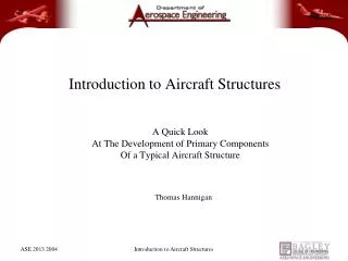
AIRCRAFT STRUCTURES-II INTRODUCTION
Course Objective • The purpose of the course is to teach the principles of solid and structural mechanics that can be used to design and analyze aerospace structures, in particular aircraft structures.
Function of Aircraft Structures General The structures of most flight vehicles are thin walled structures (shells) Resists applied loads (Aerodynamic loads acting on the wing structure) Provides the aerodynamic shape Protects the contents from the environment
Definitions Primary structure: A critical load-bearing structure on an aircraft. If this structure is severely damaged, the aircraft cannot fly. Secondary structure: Structural elements mainly to provide enhanced aerodynamics. Fairings, for instance, are found where the wing meets the body or at various locations on the leading or trailing edge of the wing.
FUSELAGE FUSELAGE • 1: Subsonic • 2: High-speed / supersonic • 3: High-capacity subsonic • 4: High-maneuverability supersonic • 5: Flying boat • 6: Hypersonic
TYPES OF FUSELAGE STRUCTURE • TRUSS-TYPE FUSELAGE STRUCTURE • MONOCOQUE FUSELAGE STRUCTURE • SEMI-MONOCOQUE FUSELAGE STRUCTURE
TRUSS-TYPE FUSELAGE STRUCTURE • The truss structure, on the other hand, is not a streamlined shape. In this construction method, lengths of tubing, called longerons, are welded in place to form a well-braced framework. Vertical and horizontal struts are welded to the longerons and give the structure a square or rectangular shape when viewed from the end. Additional struts are needed to resist stress that can come from any direction. Stringers and bulkheads, or formers, are added to shape the fuselage and support the covering
Monocoque-semimono • Monocoque is a French word meaning "single shell." It describes a type of construction used on a plane's fuselage in which wooden hoops are shaped over a curved form and then glued. Braces usually run the length of the fuselage (semi-monocoque). Strips of plywood are glued over this form. Most twisting and bending stresses are carried by the external skin rather than by an open framework, eliminating the need for internal bracing and resulting in a more streamlined airplane than with a truss-type fuselage. The first wood monocoque structure was designed by the Swiss Ruchonnet and applied to a Deperdussin monoplane racer by Louis Béchereau in 1912. This term is sometimes used interchangeably with "stressed-skin," which was originally meant to apply to the structure of wings and tail-surfaces that were laid over metal spars.
Definitions… Monocoque structures: Unstiffened shells. must be relatively thick to resist bending, compressive, and torsional loads.
Definitions… Semi-monocoque Structures: Constructions with stiffening members that may also be required to diffuse concentrated loads into the cover. More efficient type of construction that permits much thinner covering shell.
WING • The wings are airfoils attached to each side of the fuselage and are the main lifting surfaces that support the airplane in flight. • There are numerous wing designs, sizes, and shapes used by the various manufacturers. Each fulfils a certain need with respect to the expected performance for the particular airplane.
TYPES OF WING SEMI CANTILEVER WING CANTILEVER WING
Wing classification • POSITION OF THE WING • CLASSIFICATION BY CONFIGURATION • INGPOSITION OF THE WING • LOW WING • MID WING • HIGH WING • NUMBER OF WINGS • MONO PLANE • BI PLANE • TRI PLANE • SHAPE OF THE WINGS • DELTA WING • DIAMOND WING • SWEPT WING • GULL SHAPED WING • POSITION OF THE WINGS • CONVENTIONAL WING • NO TAIL OR TAILESS • HORIZONTAL TAIL LOCATED AOVE THE VERTICAL TAIL • CANARD TYPE • MID WING • HIGH WING • NUMBER OF WINGS • MONO PLANE • BI PLANE • TRI PLANE • SHAPE OF THE WINGS • DELTA WING • DIAMOND WING • SWEPT WING • GULL SHAPED WING • POSITION OF THE WINGS • CONVENTIONAL WING • NO TAIL OR TAILESS • HORIZONTAL TAIL LOCATED AOVE THE VERTICAL TAIL • CANARD TYPE
Low wing - mounted on the lower fuselage. • Mid wing - mounted approximately half way up the fuselage. • High wing- mounted on the upper fuselage. • Shoulder wing - a high wing mounted on the upper part of the main fuselage (as opposed to mounting on the cockpit fairing or similar).
Function of Aircraft Structures:Part specific Skin reacts the applied torsion and shear forces transmits aerodynamic forces to the longitudinal and transverse supporting members acts with the longitudinal members in resisting the applied bending and axial loads acts with the transverse members in reacting the hoop, or circumferential, load when the structure is pressurized.
Function of Aircraft Structures:Part specific Ribs and Frames • Structural integration of the wing and fuselage • Keep the wing in its aerodynamic profile
Function of Aircraft Structures:Part specific Spar • resist bending and axial loads • form the wing box for stable torsion resistance
Function of Aircraft Structures:Part specific • Stiffener or Stringers • resist bending and axial loads along with the skin • divide the skin into small panels and thereby increase its buckling and failing stresses • act with the skin in resisting axial loads caused by pressurization.
Simplifications • The behavior of these structural elements is often idealized to simplify the analysis of the assembled component • Several longitudinal may be lumped into a single effective • longitudinal to shorten computations. • The webs (skin and spar webs) carry only shearing stresses. • The longitudinal elements carry only axial stress. • The transverse frames and ribs are rigid within their own planes, so that the cross section is maintained unchanged during loading.
UNIT-IUnsymmetric Bending of Beams The learning objectives of this chapter are: •Understand the theory, its limitations, and its application in design and analysis of unsymmetric bending of beam.
UNIT-IUNSYMMETRICAL BENDING (II.1) The general bending stress equation for elastic, homogeneous beams is given as where Mx and My are the bending moments about the x and y centroidal axes, respectively. Ix and Iy are the second moments of area (also known as moments of inertia) about the x and y axes, respectively, and Ixy is the product of inertia. Using this equation it would be possible to calculate the bending stress at any point on the beam cross section regardless of moment orientation or cross-sectional shape. Note that Mx, My, Ix, Iy, and Ixy are all unique for a given section along the length of the beam. In other words, they will not change from one point to another on the cross section. However, the x and y variables shown in the equation correspond to the coordinates of a point on the cross section at which the stress is to be determined.
Neutral Axis: • When a homogeneous beam is subjected to elastic bending, the neutral axis (NA) will pass through the centroid of its cross section, but the orientation of the NA depends on the orientation of the moment vector and the cross sectional shape of the beam. • When the loading is unsymmetrical (at an angle) as seen in the figure below, the NA will also be at some angle - NOT necessarily the same angle as the bending moment. • Realizing that at any point on the neutral axis, the bending strain and stress are zero, we can use the general bending stress equation to find its orientation. Setting the stress to zero and solving for the slope y/x gives (
UNIT-IISHEAR FLOW AND SHEAR CEN Restrictions: Shear stress at every point in the beam must be less than the elastic limit of the material in shear. Normal stress at every point in the beam must be less than the elastic limit of the material in tension and in compression. Beam's cross section must contain at least one axis of symmetry. The applied transverse (or lateral) force(s) at every point on the beam must pass through the elastic axis of the beam. Recall that elastic axis is a line connecting cross-sectional shear centers of the beam. Since shear center always falls on the cross-sectional axis of symmetry, to assure the previous statement is satisfied, at every point the transverse force is applied along the cross-sectional axis of symmetry. The length of the beam must be much longer than its cross sectional dimensions. The beam's cross section must be uniform along its length.
Shear Center If the line of action of the force passes through the Shear Center of the beam section, then the beam will only bend without any twist. Otherwise, twist will accompany bending. The shear center is in fact the centroid of the internal shear force system. Depending on the beam's cross-sectional shape along its length, the location of shear center may vary from section to section. A line connecting all the shear centers is called the elastic axis of the beam. When a beam is under the action of a more general lateral load system, then to prevent the beam from twisting, the load must be centered along the elastic axis of the beam.
Shear Center • The two following points facilitate the determination of the shear center location. • The shear center always falls on a cross-sectional axis of symmetry. • If the cross section contains two axes of symmetry, then the shear center is located at their intersection. Notice that this is the only case where shear center and centroid coincide.
SHEAR STRESS DISTRIBUTION RECTANGLE T-SECTION
EXAMPLES • For the beam and loading shown, determine: (a) the location and magnitude of the maximum transverse shear force 'Vmax', (b) the shear flow 'q' distribution due the 'Vmax', (c) the 'x' coordinate of the shear center measured from the centroid, (d) the maximun shear stress and its location on the cross section. Stresses induced by the load do not exceed the elastic limits of the material. NOTE:In this problem the applied transverse shear force passes through the centroid of the cross section, and not its shear center. FOR ANSWER REFER http://www.ae.msstate.edu/~masoud/Teaching/exp/A14.7_ex3.html
Shear Flow Analysis for Unsymmetric Beams • SHEAR FOR EQUATION FOR UNSUMMETRIC SECTION IS
SHEAR FLOW DISTRIBUTION • For the beam and loading shown, determine: • (a) the location and magnitude of the maximum transverse shear force, • (b) the shear flow 'q' distribution due to 'Vmax', • (c) the 'x' coordinate of the shear center measured from the centroid of the cross section. • Stresses induced by the load do not exceed the elastic limits of the material. The transverse shear force is applied through the shear center at every section of the beam. Also, the length of each member is measured to the middle of the adjacent member. • ANSWER REFER • http://www.ae.msstate.edu/~masoud/Teaching/exp/A14.8_ex1.html
Beams with Constant Shear Flow Webs Assumptions: • Calculations of centroid, symmetry, moments of area and moments of inertia are based totally on the areas and distribution of beam stiffeners. • A web does not change the shear flow between two adjacent stiffeners and as such would be in the state of constant shear flow. • The stiffeners carry the entire bending-induced normal stresses, while the web(s) carry the entire shear flow and corresponding shear stresses.
Analysis • Let's begin with a simplest thin-walled stiffened beam. This means a beam with two stiffeners and a web. Such a beam can only support a transverse force that is parallel to a straight line drawn through the centroids of two stiffeners. Examples of such a beam are shown below. In these three beams, the value of shear flow would be equal although the webs have different shapes. • The reason the shear flows are equal is that the distance between two adjacent stiffeners is shown to be 'd' in all cases, and the applied force is shown to be equal to 'R' in all cases. The shear flow along the web can be determined by the following relationship
Important Features of Two-Stiffener, Single-Web Beams: • Shear flow between two adjacent stiffeners is constant. • The magnitude of the resultant shear force is only a function of the straight line between the two adjacent stiffeners, and is absolutely independent of the web shape. • The direction of the resultant shear force is parallel to the straight line connecting the adjacent stiffeners. • The location of the resultant shear force is a function of the enclosed area (between the web, the stringers at each end and the arbitrary point 'O'), and the straight distance between the adjacent stiffeners. This is the only quantity that depends on the shape of the web connecting the stiffeners. • The line of action of the resultant force passes through the shear center of the section.
EXAMPLE • For the multi-web, multi-stringer open-section beam shown, determine (a) the shear flow distribution, (b) the location of the shear center • Answer
UNIT-IIITorsion of Thin - Wall Closed Sections • Derivation Consider a thin-walled member with a closed cross section subjected to pure torsion.
Examining the equilibrium of a small cutout of the skin reveals that